4579
Central SNR Gain from the Field Strength: Evaluation of Current RF Coil Technology
Alireza Sadeghi-Tarakameh1, Andrea Grant1, Matt Waks1, Nader Tavaf1, Russell L Lagore1, Lance DelaBarre1, Edward Auerbach1, Gregor Adriany1, Pierre‐Francois Van de Moortele1, Kamil Ugurbil1, and Yigitcan Eryaman1
1Center for Magnetic Resonance Research (CMRR), University of Minnesota, Minneapolis, MN, United States
1Center for Magnetic Resonance Research (CMRR), University of Minnesota, Minneapolis, MN, United States
Synopsis
Keywords: RF Arrays & Systems, High-Field MRI
Higher signal-to-noise ratio (SNR) is the primary motivation for increasing the magnetic field strength of MRI scanners. However, advanced technology, including state-of-art radiofrequency receiver coils, is strictly required to realize the SNR gain from field strength. In this study, we experimentally investigate the capability of conventional loop technology to capture central SNR gain from field strength for head applications. For this purpose, we evaluated the SNR performance of several loop receiver arrays at 3T, 7T, and 10.5T. We showed that realizing the SNR gain from the UHF will likely require RF coil technologies other than the conventional receiver loop arrays.Introduction
The promise of increased SNR1-5 with higher field strength, is drawing significant attention to ultrahigh field (UHF, defined as ≥7T) scanners, especially for head imaging applications. The ultimate intrinsic SNR (UISNR)3 calculations inside a uniform spherical phantom6,7 show that the UISNR at the center increases almost quadratically with the field strength (B0). Numerical calculations8 suggest that the conventional RF coil technology based on the array of loop elements can capture a significant portion (>90%) of the UISNR—which defines the highest achievable SNR— at the center of a uniform spherical phantom. Numerical simulation results9 show that receiver array coils with different numbers of loop elements (from 8 to 96) almost equally capture the UISNR at the center at different field strengths (from 1.5T to 9.4T). In contrast, they show that the coils’ SNR performances at peripheral regions significantly increase with the number of loop elements yet remain far below (~10%) the UISNR value9. The promise of capturing central UISNR, as well as peripheral SNR increase with the number of loop elements, motivates the utilization of conventional loop array technology with a higher number of loop elements for many coil developments at different field strengths10-14, including UHF.In this study, we experimentally investigate the capability of conventional loop technology to capture central SNR gain from field strength for head applications. For this purpose, we evaluate the SNR performance of several commercial, as well as custom-built, loop receiver arrays with different numbers of loops at three field strengths (3T, 7T, and 10.5T) inside a uniform spherical phantom.
Methods
MRI ScannersMRI experiments were conducted at 3T (Prisma, Siemens Healthineers, Erlangen, Germany), 7T (Magnetom, Siemens Healthineers, Erlangen, Germany), and 10.5T (Magnetom, Siemens Healthineers, Erlangen, Germany) MRI scanners.
3T Reciever Coils
SNR measurements at 3T were performed using three commercial receiver coils: 20-channel head/neck coil (Head/Neck 20, Siemens Healthineers), 32-channel head coil (Head 32, Siemens Healthineers), and 64-channel head/neck coil (Head/Neck 64, Siemens Healthineers).
7T Reciever Coils
SNR measurements at 7T were performed using two commercial and one custom-built receiver coils: birdcage tune-up service coil (QED, Mayfield Village, Ohio, USA), 32-channel head coil (Nova Medical Inc., Wilmington, MA), and 64-channel head coil (custom-built13).
10.5T Reciever Coils
SNR measurements at 10.5T were performed using one commercial and one custom-built receiver coils: birdcage tune-up service coil (QED, Mayfield Village, Ohio, USA) and 64-channel head coil (custom-built15).
SNR Measurements and Analyses
SNR data were acquired with fully sampled 2D GRE sequences with a long TR for full relaxation at all field strengths (TR=10000ms, TE=3.8ms, full bandwidth = 87.04kHz, matrix size = 84×256, FOV = 256×168mm, voxel size = 2.0 × 1.0 × 2.0mm). Noise images were acquired with identical parameters, but the flip angle was set to 0, and TR was reduced to 1000ms. SNR was normalized to flip angle using Actual Flip Angle (AFI)16 and was converted to intrinsic SNR as previously described13.
All SNR measurements were performed inside a polyvinylpyrrolidone (PVP)-based uniform spherical phantom with an inner diameter of 16.5cm. The electrical properties of the phantom were measured using a commercial probe (DAKS-12, SPEAG, Zurich, Switzerland) at three field strengths as follows: 3T—(εr=55, σ=0.47S/m); 7T—(εr=51, σ=0.56S/m); 10.5T—(εr=48, σ=0.65S/m).
To evaluate the SNR performances of the coils at different depths from surface of the phantom, 3D SNR data were averaged inside spherical-shell ROIs with a thickness of 1cm at different depths. Central SNR was averaged inside a sphere with a 1cm radius.
Results
Fig. 1A shows the intrinsic SNR maps of the 3T coils on axial and sagittal planes. Fig. 1B presents a comparison between the intrinsic SNRs of these coils at different depths.Similarly, Fig. 2 and Fig. 3, respectively, demonstrate the SNR performances of the 7T and 10.5T coils.
The solid line in Fig. 4 shows the B0-dependence of the central SNR of the state-of-art 64-channel coils (data points are normalized to the 10.5T SNR value). The dashed line presents the quadratic B0-dependence model17 that takes the 3T SNR value as a reference and translates it to 7T and 10.5T.
Discussions and Conclusion
In this study, we experimentally investigate the capability of conventional loop technology to capture the central SNR gain from field strength for head applications. Despite the theoretical and numerical predictions, 64-channel loop receiver arrays fail to achieve the quadratic central SNR increase expected at 7T and 10.5T. It is noteworthy that, at 10.5T, the birdcage coil outperforms the 64-channel coil’s central SNR by 45%. To recover the central SNR at 10.5T, we have extended our previously proposed novel technology based on a loop-dipole hybrid array18 to human head application and boosted central SNR up to 70% (corresponding abstracts are submitted to the ISMRM).This study shows that realizing the SNR gain from the UHF will likely require RF coil technologies other than the conventional receiver loop arrays. Also, the numerically proven hypothesis that the higher number of loops does not improve the central SNR is validated at 3T and 7T.
Acknowledgements
This work was supported by the following grants: NIBIB P41 EB027061, NINDS R01NS115180 and NIH U01 EB025144.References
- Vaughan JT, Garwood M, Collins CM, Liu W, DelaBarre L, Adriany G, Andersen P, Merkle H, Goebel R, Smith MB. 7T vs. 4T: RF power, homogeneity, and signal‐to‐noise comparison in head images. Magnetic Resonance in Medicine: An Official Journal of the International Society for Magnetic Resonance in Medicine. 2001;46(1):24-30.
- Pohmann R, Speck O, Scheffler K. Signal‐to‐noise ratio and MR tissue parameters in human brain imaging at 3, 7, and 9.4 tesla using current receive coil arrays. Magnetic resonance in medicine. 2016;75(2):801-9.
- Ocali O, Atalar E. Ultimate intrinsic signal‐to‐noise ratio in MRI. Magnetic resonance in medicine. 1998;39(3):462-73.
- Wiesinger F, Boesiger P, Pruessmann KP. Electrodynamics and ultimate SNR in parallel MR imaging. Magnetic Resonance in Medicine: An Official Journal of the International Society for Magnetic Resonance in Medicine. 2004;52(2):376-90.
- Guérin B, Villena JF, Polimeridis AG, Adalsteinsson E, Daniel L, White JK, Wald LL. The ultimate signal‐to‐noise ratio in realistic body models. Magnetic resonance in medicine. 2017;78(5):1969-80.
- Lee HH, Sodickson DK, Lattanzi R. An analytic expression for the ultimate intrinsic SNR in a uniform sphere. Magnetic resonance in medicine. 2018;80(5):2256-66.
- Hoult DI. Sensitivity and power deposition in a high‐field imaging experiment. Journal of Magnetic Resonance Imaging. 2000;12(1):46-67.
- Lattanzi R, Sodickson DK. Ideal current patterns yielding optimal signal‐to‐noise ratio and specific absorption rate in magnetic resonance imaging: computational methods and physical insights. Magnetic resonance in medicine. 2012;68(1):286-304.
- Vaidya MV, Sodickson DK, Lattanzi R. Approaching ultimate intrinsic SNR in a uniform spherical sample with finite arrays of loop coils. Concepts in Magnetic Resonance Part B: Magnetic Resonance Engineering. 2014 Aug;44(3):53-65.
- Wiggins GC, Triantafyllou C, Potthast A, Reykowski A, Nittka M, Wald LL. 32‐channel 3 Tesla receive‐only phased‐array head coil with soccer‐ball element geometry. Magnetic Resonance in Medicine: An Official Journal of the International Society for Magnetic Resonance in Medicine. 2006 Jul;56(1):216-23.
- Keil B, Blau JN, Biber S, Hoecht P, Tountcheva V, Setsompop K, Triantafyllou C, Wald LL. A 64‐channel 3T array coil for accelerated brain MRI. Magnetic resonance in medicine. 2013 Jul;70(1):248-58.
- Wiggins GC, Polimeni JR, Potthast A, Schmitt M, Alagappan V, Wald LL. 96‐Channel receive‐only head coil for 3 Tesla: design optimization and evaluation. Magnetic Resonance in Medicine: An Official Journal of the International Society for Magnetic Resonance in Medicine. 2009 Sep;62(3):754-62.
- Uğurbil K, Auerbach E, Moeller S, Grant A, Wu X, Van de Moortele PF, Olman C, DelaBarre L, Schillak S, Radder J, Lagore R. Brain imaging with improved acceleration and SNR at 7 Tesla obtained with 64‐channel receive array. Magnetic resonance in medicine. 2019 Jul;82(1):495-509.
- May MW, Hansen SL, Mahmutovic M, Scholz A, Kutscha N, Guerin B, Stockmann JP, Barry RL, Kazemivalipour E, Gumbrecht R, Kimmlingen R. A patient‐friendly 16‐channel transmit/64‐channel receive coil array for combined head–neck MRI at 7 Tesla. Magnetic Resonance in Medicine. 2022 May 23.
- Tavaf N, Jungst S, Lagore RL, Radder J, Moeller S, Grant A, Auerbach E, Ugurbil K, Adriany G, Van de Moortele PF. A Self-decoupled 64 Channel Receive Array for Human Brain MRI at 10.5T. In Proceedings of the 2021 ISMRM & SMRT Annual Meeting & Exhibition, 2021. p. 0179.
- Yarnykh VL. Actual flip-angle imaging in the pulsed steady state: a method for rapid three-dimensional mapping of the transmitted radiofrequency field. Magn Reson Med. 2007; 57: 192- 200.
- Le Ster C, Grant A, Van de Moortele PF, Monreal‐Madrigal A, Adriany G, Vignaud A, Mauconduit F, Rabrait‐Lerman C, Poser BA, Uğurbil K. Magnetic field strength dependent SNR gain at the center of a spherical phantom and up to 11. 7T. Magnetic resonance in medicine. 2022;88(5):2131-8.
- Lagore RL, Moeller S, Zimmermann J, DelaBarre L, Radder J, Grant A, Ugurbil K, Yacoub E, Harel N, Adriany G. An 8‐dipole transceive and 24‐loop receive array for non‐human primate head imaging at 10.5 T. NMR in Biomedicine. 2021 Apr;34(4):e4472.
Figures
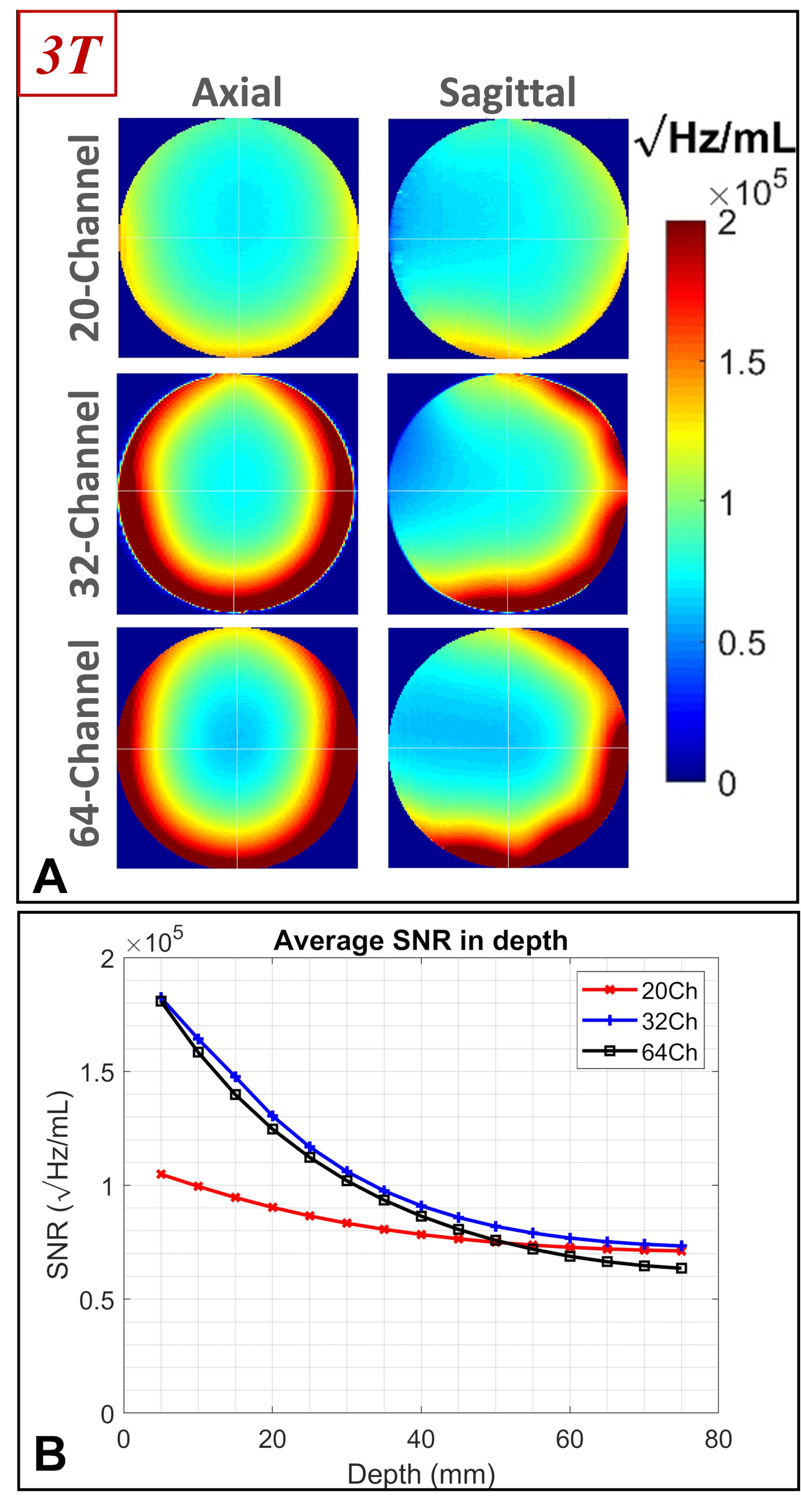
Figure 1. SNR performance of three receiver coils at 3T. (A) Intrinsic
SNR maps on axial and sagittal planes corresponding to the 20ch, 32ch, and 64ch
coils. (B) Intrinsic SNR of the three coils as a function of the radial distance
from the surface of a spherical phantom.
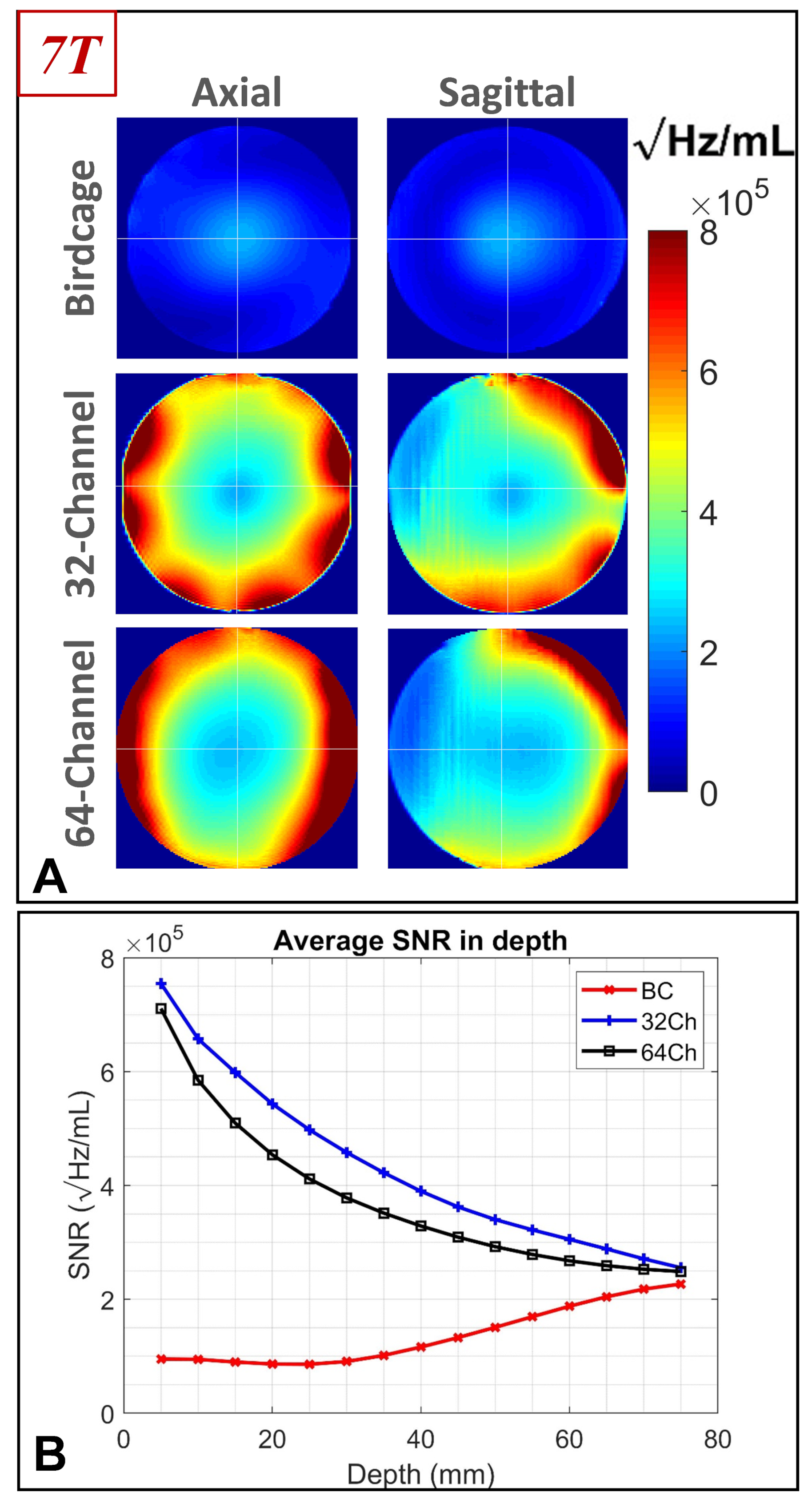
Figure 2. SNR performance of three receiver coils at 7T. (A) Intrinsic
SNR maps on axial and sagittal planes corresponding to the birdcage, 32ch (NOVA), and 64ch coils. (B)
Intrinsic SNR of the three coils as a function of the radial distance from the surface
of a spherical phantom.
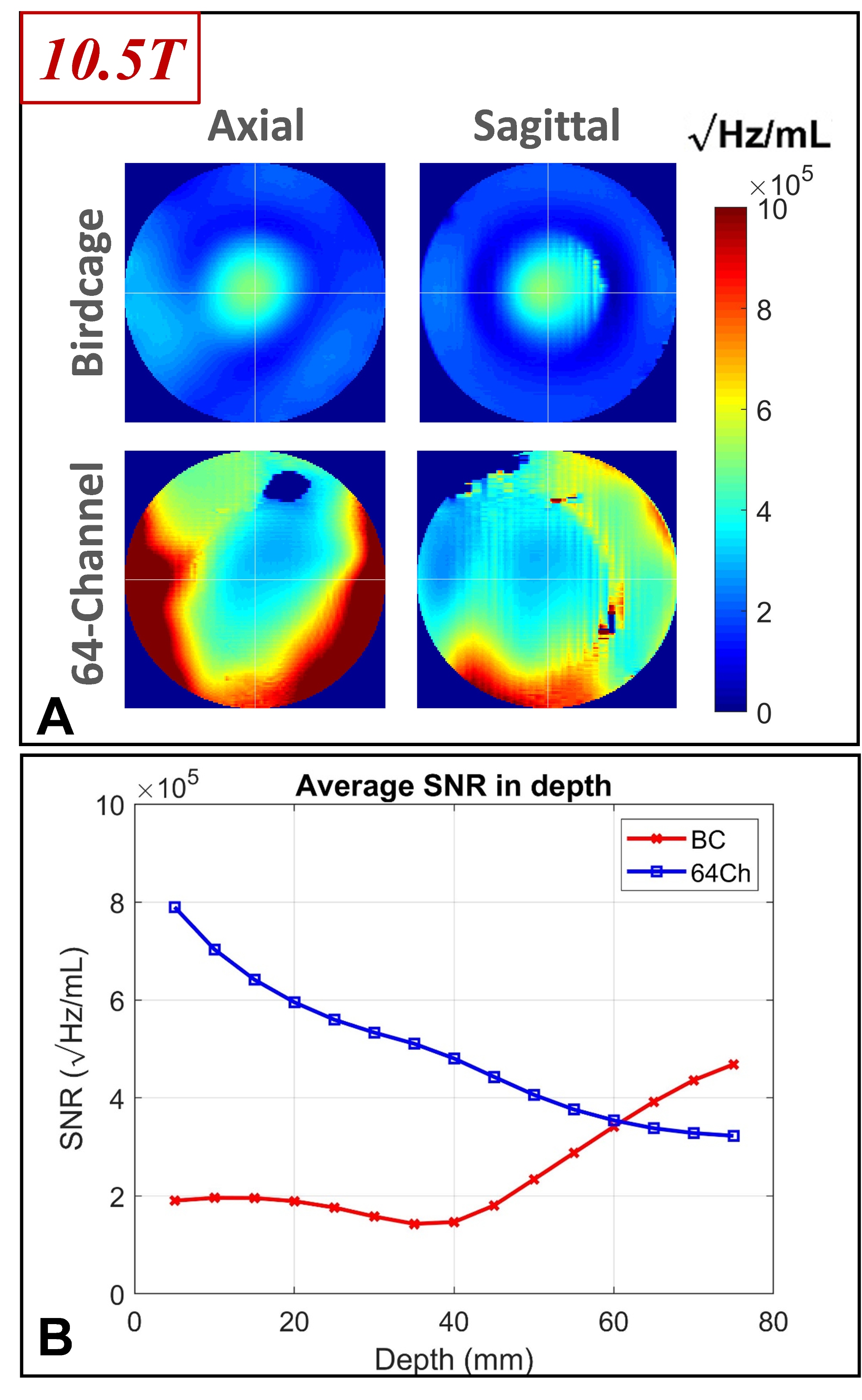
Figure 3. SNR performance of two receiver coils at 10.5T. (A) Intrinsic SNR maps on axial and sagittal
planes corresponding to the birdcage and 64ch coils. (B) Intrinsic SNR of the two coils as a function of the radial distance
from the surface of a spherical phantom.
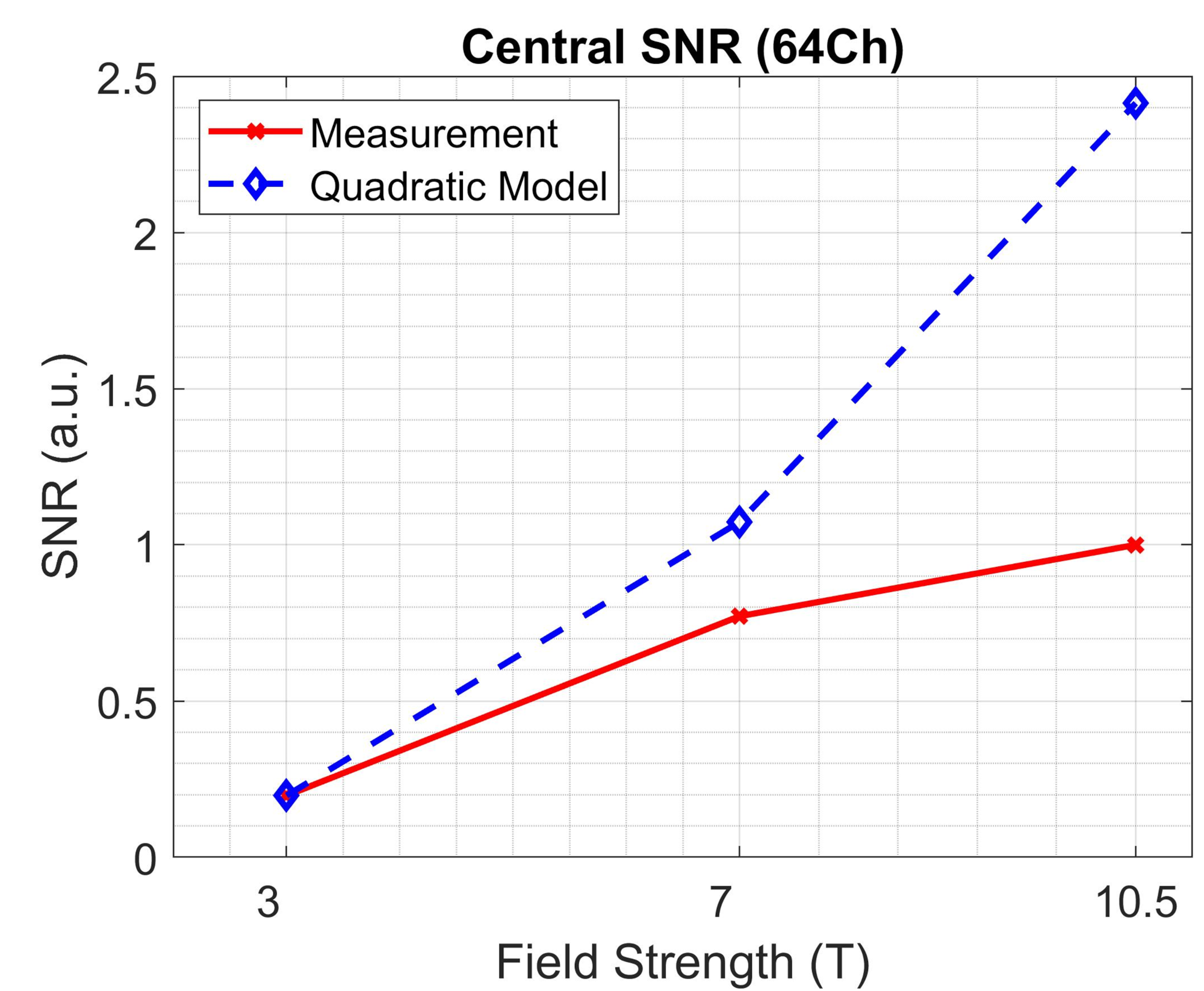
Figure 4. Measured
central SNR corresponding to 64-channel loop receiver array coils at 3T, 7T,
and 10.5T. The measured SNR values are normalized to that of 10.5T. The dashed
line is corresponding to the theoretically proposed quadratic model, which
translates the measured SNR at 3T to 7T and 10.5T.
DOI: https://doi.org/10.58530/2023/4579