4576
Open-source, low-cost device for visualizing static magnetic field components at 0.25 T and 3 T1Elmore Family School of Electrical and Computer Engineering, Purdue University, West Lafayette, IN, United States, 2Weldon School of Biomedical Engineering, Purdue University, West Lafayette, IN, United States
Synopsis
Keywords: Magnets (B0), New Devices
We present a low-cost (<$17 USD per channel), open-source, and scalable prototype for visualizing the three-axis static magnetic field components up to 3 T based on the GaAs Hall effect technology. The prototype showed accuracy and stability on the bench and accurately measured field values in a 0.25 T electromagnet and a 3 T MRI scanner.Motivation
B0 field homogeneity is critical to the quality control of MRI, with inhomogeneity affecting signal uniformity and spatial integrity, and potentially generating image artifacts. The spectrum full width at half maximum (FWHM) is typically used to evaluate the B0 homogeneity within the scanner1. Gradient mapping is also important for the gradient nonlinearity correction in quantitative diffusion MRI2. Magnetic field sensors allow for the precise external measurement of the changing magnetic fields. Commercial magnetic field “cameras” that work at MR scanner field levels cost in the order of thousands of USD and come in fixed, non-customizable dimensions. The use of the 1D and 3D Hall effect magnetometers for MRI have been proposed3 but most implementations rely on custom-developed prototypes and do not provide adequate mT-order resolution4.We present a low cost (< $17 USD per channel), open-source, scalable device for visualizing the three-axis static magnetic field components for up to 3 T.
Design
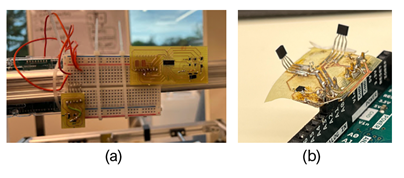
We use a GaAs Hall effect sensor (CYSJ362A, ChenYang Technologies, Germany) which senses the magnetic field component in the chip plane. This sensor has dimensions 2.7 x 2.35 x 0.95 mm and has a measurement range of 100 mT to 3 T with 2% linearity. The measured sensitivity of the sensors is 16 mV/T. Three sensors are placed in each magnetic component direction on an in-house fabricated printed circuit board (PCB) (Fig 1). Separate signal conditioning chains are applied to each sensor. A constant 5 V DC is supplied to the sensors, and the sensor output is connected to an internal differential amplifier, where the DC offset (±8 mV) is cancelled, and the signal amplified to 0 – 5V (0 – 3 T). The output after the conditioning chain is proportional to the applied magnetic field. The output is connected to a 12-bit analog-to-digital converter (ADC) which is read by an ATmega2560 microcontroller (Microchip Technology, USA), which is then passed through a serial interface to an in-house MATLAB (MathWorks, USA) script that performs calibration and field mapping. The sensor setup is attached to a nylon wand to allow precise positional control of the sensor.Testing
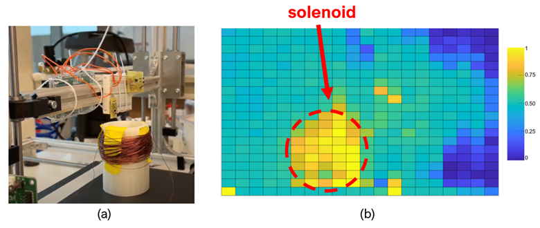
Bench testA hand-wound solenoid electromagnet is constructed and supplied with 20 VDC. The sensor setup is attached to a modified CNC rig which has a 1 mm spatial resolution (Fig 2a). The MATLAB script controls the movement of the CNC rig (using real-time g-code) and reads the output sent from the microcontroller.
0.25 T testing
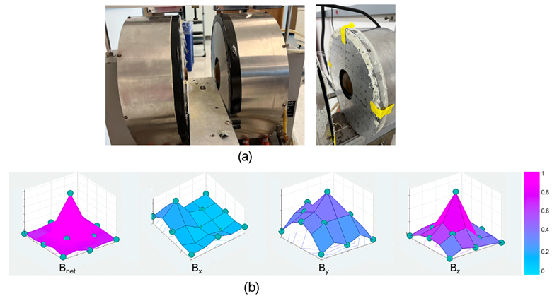
19.5 A at 40 VDC is applied to a 1 T electromagnet, inducing a constant 0.25 T B-field in the pole-to-pole direction. The connected sensor is measured on a sampling grid of 12 x 12 x 8 cm (2 cm resolution) (Fig 3a). The sampled data is interpolated in MATLAB using a triangular mesh.
3 T MRI scanner testing
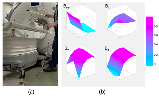
The sensor setup is tested on the 3 T Discovery MR750 (GE Healthcare, USA) MRI scanner. A 5 m serial cable connects the sensor to the computer located outside the scanner room (Fig 4a). The region above the scanner bed outside the bore was measured to visualize the fringe fields. Measurement on a grid of 3 cm resolution was performed and interpolated in the same manner.
Results and discussion
Bench testing demonstrated that the Hall effect sensor was able to measure minute changes in the magnetic field. The field map shows distinct magnetic field strengths inside and outside the solenoid (Fig 2b). The 0.25 T field testing accurately measures the magnetic field in 3 directions, with the z-axis showing the greatest field strength (Fig 3b). Testing at the 3T scanner shows the expected B0 magnetic field strength and fringe fields along the outside of the bore (Fig 4b). There is some variability due to the manual measurement at each sampling location. The total cost of the setup is $16.8 USD, which includes the Hall effect sensor, the microcontroller, and cost of PCB production.Conclusion
We have presented a first prototype of a magnetic field strength sensor for MRI scanners based on the GaAs Hall effect sensor. The experimental results demonstrate that an inexpensive Hall sensor can be implemented in simple hardware to reasonably measure the magnetic field strength.For applications requiring the measurement of fast-changing gradients, a more precise ADC and microcontroller could be used to provide improved signal conditioning. With proper post-processing and calibration, this prototype will be able to detect magnetic fields with the same accuracy and precision as commercial counterparts. Future work include testing the array during scan sequences, developing a large array of sensors for parallel sensing, and developing an automated procedure for mapping the entire MR bore.
Acknowledgements
The authors would like to thank the ISMRM MR Engineering Study Group and its ISMRM Engineering Challenge. The authors also thank Kirk S. Foster for his help in setting up the 1 T electromagnet.
References
1. Ishimori Y, Kawamura H, Monma M. Evaluation of magnetic field homogeneity using in-out signal cycle mapping in gradient recalled echo images of a mixed water/oil phantom as a rough indication for daily quality control. J Biomed Graph Comput. 2016; 6
2. Barnett AS, Irfanoglu MO, Landman B, Rogers B, Pierpaoli C. Mapping gradient nonlinearity and miscalibration using diffusion‐weighted MR images of a uniform isotropic phantom. Magn Reson Med. 2021; 86:3259.
3. Scheffler K. Magnetic field sensor-based navigation system to track MR image-guided interventional procedures. US Patent Number US7650178B2. 2010
4. Schell JB, Kammerer JB, Hebrard L, et al. Towards a Hall effect magnetic tracking device for MRI. Annu. Int. Conf. IEEE Eng. Med. Biol. Proc. 2013; 2964–2967
Figures