4573
A Novel Method to Estimate and Control the Eddy Power Loss within the Cryostat: A Co-Simulation Approach to Tune Z-Gradient Array Coil1UMRAM, Bilkent University, Ankara, Turkey, 2Electrical and Electronics Engineering, Bilkent University, Ankara, Turkey
Synopsis
Keywords: Gradients, Hybrid & Novel Systems Technology, Gradient Array Coils
We propose a fast computational method based on a series of electromagnetic simulations to calculate a proper set of feeding currents for a z-gradient array coil that dynamically provides the best shield for its primary array coil. The net magnetic field generated by each array element is calculated, and the total average eddy power (energy) loss resulting from fast-switching stray fields inside the cryostat assembly is estimated and controlled. Two design scenarios with comparable performance criteria are offered for a 48-element z-gradient array coil. The accuracy of the estimated eddy power losses is compared with that of commercial software.Introduction
Tunable array coils1-6 enable dynamic adjustments to imaging volume parameters such as gradient intensity, ROI size and position, and linearity error. Aside from manufacturing issues, calculating cryostat heating caused by complicated induced eddy currents is difficult. We propose an approach to estimate and control the average eddy power loss within the cryostat body and reduce the thermal load. Compared to recent array design methods4-6, which are partially based on canceling out the stray fields on the warm bore, it provides a fast and accurate solution to find a proper set of feeding currents that also satisfy other design constraints.Methods
For a z-gradient array coil, both axial and radial components of the net magnetic field (the field created by the gradient coils plus the field caused by the induced currents) are independent of $$$\varphi$$$. Figure 1 depicts a simplified half-cross-section view of a cylindrical cryostat assembly with four vertices ($$$a$$$ to $$$d$$$). Assume $$$H_{z_n}(\rho,z)$$$ and $$$H_{{\rho}_n}(\rho,z)$$$ are the net axial and radial magnetic fields on the surface of the cryostat, generated by the $$$n$$$th array element of unity excitation. To minimize the eddy power loss within the cryostat body, we introduce a fast quadratic $$${{\bar{A}}^*}^{T}\bar{\!\bar{Q}}\bar{A}$$$ minimization problem (subjected to the usual constraints of the ROI), where $$$\bar{A}_{N\times1}$$$ is the current vector for $$$N$$$ independent array elements and $$$\bar{\bar{Q}}_{N\times N}$$$ is a geometry-dependent complex-valued Hermitian matrix to be found once, using commercial EM solvers (given the dimension and structure of the array coil). The $$$\bar{\bar{Q}}$$$ matrix is defined by:| $$[\bar{\bar{Q}}]_{m,n}=2\pi\bigg\{\bigg[\!\int_{abc}\!\!\!+\!\int_{adc}\!\bigg]\rho\big[H_{z_m}^{*}(\rho,z)H_{z_n}(\rho,z)+H_{\rho_m}^{*}(\rho,z)H_{{\rho}_n}(\rho,z)\big]d\ell\bigg\};\quad m,n=1..N\quad\quad (\text{A}^2),$$ | (1) |
| $$P_{w(t)}^{Loss}(\bar{A},\sigma)\cong\frac{2\sqrt{\pi\mu_0}}{T^{5/2}\sqrt{\sigma}}{{\bar{A}}^*}^{T}\bar{\!\bar{Q}}\bar{A}\sum_{m=1}^{M\rightarrow\infty}\sqrt{m}\Big|W\Big({\frac{m}{T}}\Big)\Big|^2\quad (\text{W}),$$ | (2) |
Results
Fig. 1 shows the ROI, array elements’ relative positions in the cryostat, and other details. An Intel Xeon$$$\circledR$$$ Dell workstation of 128GB memory, the optimization toolbox of Maple 20227, and Ansys Maxwell8 2022 are utilized for numerical calculations and simulations.We present two designs and the respective field plots (1KHz excitations) over the half cross-section of the MRI device (including the array coil and the cryostat), both of which are subjected to similar constraints of <5.4% linearity deviation, 40.0mT/m gradient strength, and 45cm diameter of ROI. The maximum voltage across the elements is 2.22KV, and the maximum driving current is 300A. Figure 2 illustrates the plot of $$$\big|{H_z}\hat{a}_z+{H_\rho}\hat{a}_\rho\big|$$$ versus distance for 48 array elements of unity excitation around the cryostat cross-section.
The first design attempts to nullify the stray fields4 on 120 distinct points along the cryostat’s inner edge that converges in 42s, and the second design deploys the proposed $$${{\bar{A}}^*}^{T}\bar{\!\bar{Q}}\bar{A}$$$ minimization that lasts 4.5s to calculate. Figures 3a,b and 4a,b illustrate half-plots of $$$B_z$$$ and $$$|\overline{B}|$$$ fields for each design, separately. For the first design that only takes care of the cryostat’s inner surface, the RMS value of all feeding currents is 40.8A and the average eddy power loss (reported by Maxwell) is 6.32W. The proposed formulation in equation (2) (for the complete cryostat assembly) reads 6.34W. Corresponding values for the second design are 5.22W (17% less), 39.1A (5% less), and 5.27W, respectively.
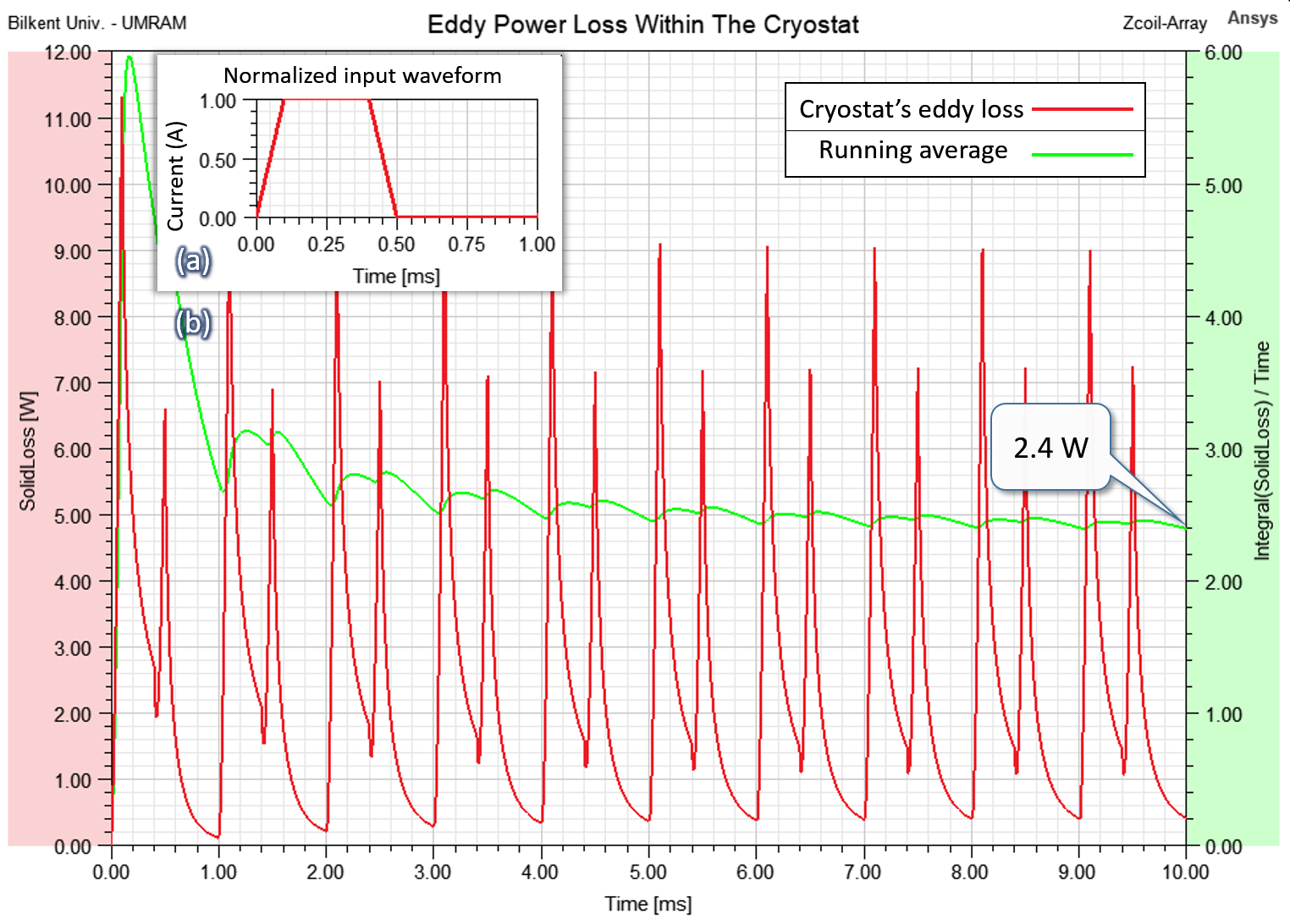
Figure 5b shows ten cycles of the second design’s transient simulation showing the instantaneous eddy power loss (and its running average) within the cryostat. The feeding waveform $$$w(t)$$$, shown in Fig. 5a, is a 1ms periodic trapezoidal waveform of 100ms rise/fall time and 300ms plateau time. For this waveform, equation (2) predicts 2.39W which agrees well with the 2.4W running average shown in the transient simulation.
Discussion
Gradient shield array coil design, either based on discrete wires or continuous currents9,10, is generally based on minimizing the stray fields on the cryostat in conjunction with other constraints governing the ROI performance parameters. Although some advanced techniques11,12 have been published to calculate the induced eddy currents, the provided solutions are computationally intensive and limited to cylindrical cases.Figure 2 shows that the dominant load for the cryostat cooling assembly is not solely due to the inner surface; other parts also contribute to the cryostat heating. The proposed approach takes a few seconds to calculate the best feeding currents that minimize the total average eddy power (or energy) loss within the cryostat body. Moreover, the estimation error is less than 1% compared to commercial simulations. By comparing the RMS values, the calculated set of currents consumes 5.7% less power than the usual design. Two case studies are simulated and compared showing the superiority, ease, and speed of predicting the eddy power losses.
Conclusion
The benefit of deploying the proposed optimization method is fourfold: (a) it takes care of power loss within the cryostat body and not just the inner cylindrical surface of the warm bore; (b) it speeds up the array tuning process and provides an accurate estimation for power (energy) losses; (c) its accuracy is comparable with commercial software; (4) it is extendable to other array coils of any shape.Acknowledgements
This research was supported by The Scientific and Technological Research Institution of Turkey (TÜBİTAK), grant number 121E128.
References
- Takrimi M and Atalar E. A Programmable Set of Z-Gradient Array and Active-Shield Array for Magnetic Resonance Imaging, ISMRM, Virtual, 2020: Abstract# 4242.
- Takrimi M and Atalar E. MRI Hybrid Gradient Coil Equipped with a Programmable Z-Array and Conventional X- and Y- Elements, ISMRM, Virtual, 2021: Abstract# 3099.
- Takrimi M and Atalar E. Z-Gradient Array Coil Equipped with a Tunable Shield Array for Creating Multiple-Imaging Volumes. In Proceedings of the 31st Annual Meeting of ISMRM, London, 2022: Abstract# 1368.
- Takrimi M and Atalar E. A z-gradient array coil with a dedicated active-shielded array coil for MRI. Magn Reson Med. 2022; 88(6):2718-2731. doi:10.1002/mrm.29390
- Littin S, Jia F, Layton KJ, et al. Development and implementation of an 84-channel matrix gradient coil. Magn Reson Med. 2018 Feb; 79(2):1181-1191. DOI: 10.1002/mrm.26700.
- Kassahun HB, Alsharafi SS, Badawi AM, El-Sharkawy A-MM. Multi-channel, actively shielded, power efficient MRI z-gradient cylindrical coil design using target-field method. IEEE Access. 2022;10:103840-103851. doi:10.1109/access.2022.3210194.
- Maple 2022. Maplesoft, a division of Waterloo Maple Inc., Waterloo, Ontario.
- https://www.ansys.com/products/electronics
- Hidalgo-Tobon S. Theory of gradient coil design methods for magnetic resonance imaging. Concepts Magn Reson. 2010; 36A:223-242. doi:10.1002/cmr.a.20163.
- Turner R. A target field approach to optimal coil design. Journal of Physics D: Applied Physics. 1986;19(8). doi:10.1088/0022-3727/19/8/001.
- Sanchez Lopez H, Poole M, Crozier S. Eddy current simulation in thick cylinders of finite length induced by coils of arbitrary geometry. Journal of Magnetic Resonance. 2010;207(2):251-261. doi:10.1016/j.jmr.2010.09.002.
- Niu C, Wang L, Wang Y, et al. Numerical Analysis of eddy current induced by Z-gradient coil in a superconducting MRI magnet. IEEE Transactions on Applied Superconductivity. 2020;30(4):1-6. doi:10.1109/tasc.2020.2969398
Figures
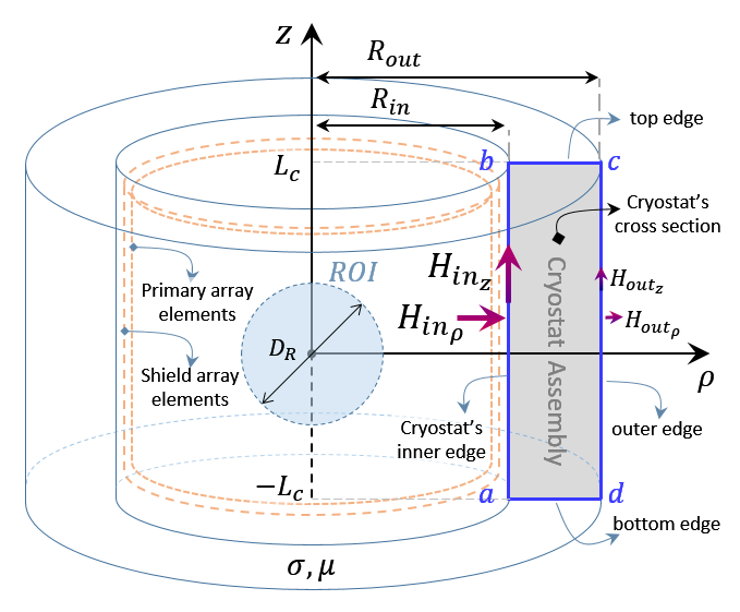
Figure 1: A cylindrical cryostat assembly of length 1.6m, radii 47cm and 78.6 cm, thickness 8mm, and conductivity 38 MS/m and its cross-section view consisting of four edges and vertices ($$$a$$$ to $$$d$$$). The axial and radial net magnetic fields on two of the edges are shown. Dashed-line cylinders show the relative position of array coil elements with respect to the cryostat. The ROI is shown by a dashed circle. Both the primary and shield array coils consist of 24 bundles of annular wire loops of 22 turns, all of which are uniformly spaced along the z-axis with an inter-bundle gap of 7mm.
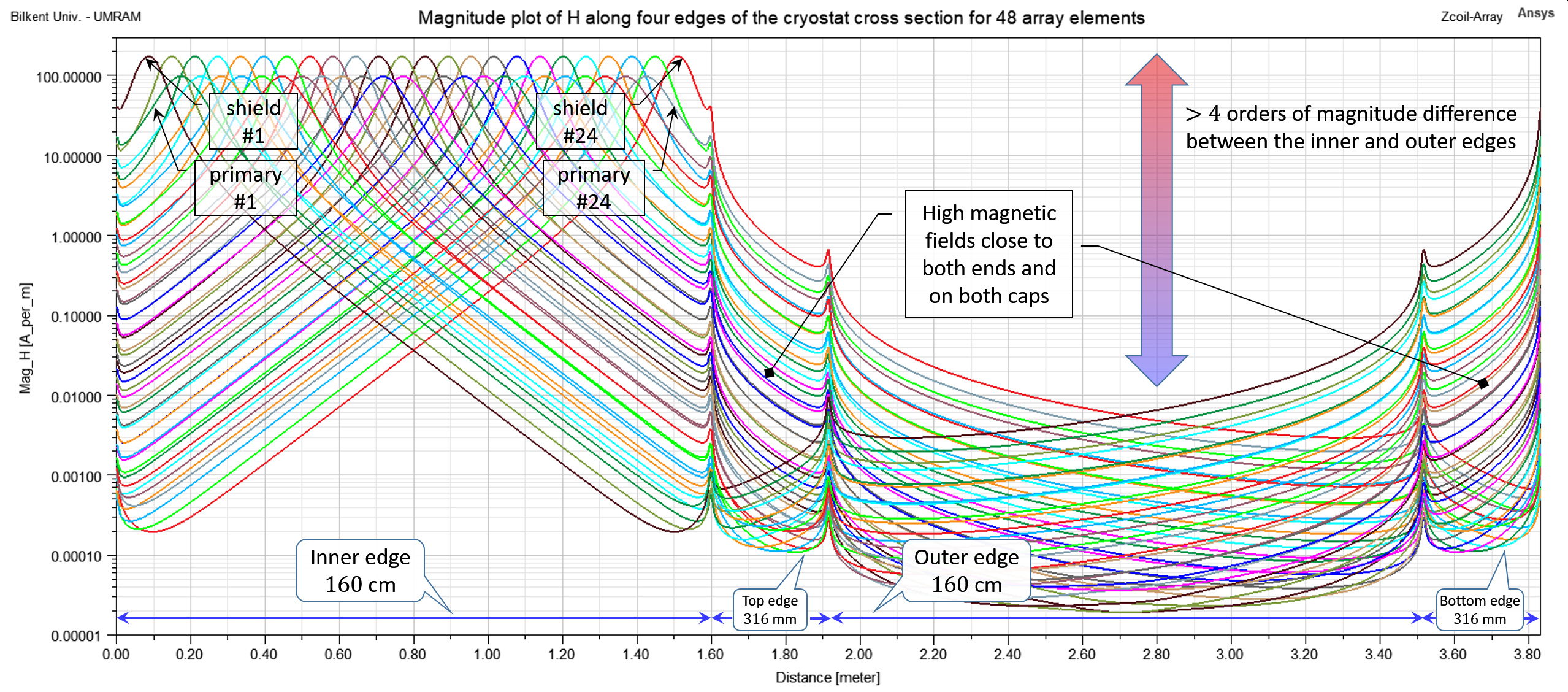
Figure 2: The logarithmic magnitude plot of $$$|\overline{H}|=|H_z\hat{a}_z+H_{\rho}\hat{a}_\rho|$$$ versus the distance by traversing $$$abcda$$$ path in Fig. 1. The path has a 160cm inner edge, a 31.6 cm top edge, a 160cm outer edge, and a 31.6 cm bottom edge. Although the inner and outer field values differ by more than four orders of magnitude, the fields at close proximity of both ends and along the caps cannot be ignored. The first (#1) and the last (#24) array elements of both primary and shield coils are labeled in the picture.
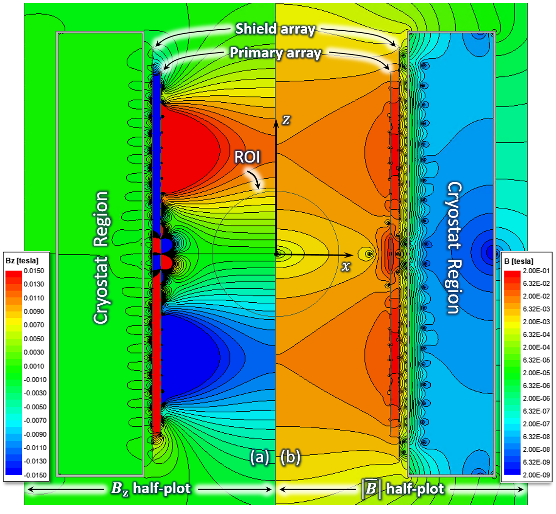
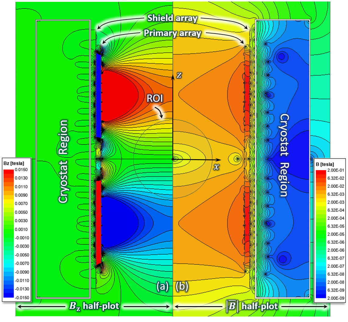
Figure 4: Half plots of (a) $$$B_z$$$ field map and (b) $$$|\overline{B}|$$$ field map for the second design based on the proposed minimization. It takes care of all four edges (surfaces) and takes 4.5s to converge. The diameter of the ROI is 45cm. The linearity error and gradient strength within the ROI are 5.2% and 40.0mT/m, respectively. The RMS value of all feeding currents is 39.1A (5% less than that of Fig. 1). Maxwell reports 5.22W for the average eddy power loss in the cryostat and the proposed formulation reads 5.27W, which is (17%) less than the first design.