4572
Thermal Model in Feedforward Control of the Gradient Array System in MRI1Department of Electrical and Electronics Engineering, Bilkent University, Ankara, Turkey, 2National Magnetic Resonance Research Center (UMRAM), Bilkent University, Ankara, Turkey
Synopsis
Keywords: Gradients, System Imperfections: Measurement & Correction
Resistive elements in a gradient system, namely the gradient coil and the amplifier, causes heating and the total system resistance to increase. With feedforward controllers, such changes cause inaccurate gradient fields to occur, which in turn causes image artifacts. To mitigate self-heating caused resistance change issues, modeling the gradient system's thermal behavior is necessary. Such a model introduces additional parameters to the overall feedforward model, and identifying these parameters correctly is essential for accurate current waveforms. For this purpose, we propose a method to extract these parameters along with a more complete thermal model.
Introduction
In MRI gradient systems, feedback control based on measuring the output current eliminates the perturbations that arise from nonlinearities and time-varying parameters. These perturbations affect recently introduced feedforward controllers1, which are preferable for gradient array and multi-coil designs2, 3. In addition to the nonlinear modeling4, the feedforward model must consider time-varying parameters due to gradient heating. Here we extend our previous study that integrated the gradient coil resistance prediction into the feedforward controller5 and added a method for obtaining thermal and electrical model parameters for both the gradient coil and the gradient power amplifier with an improved thermal model that accounts both coil and the amplifier independently.Method
The proposed system model (Figure 1) has three electrical and four thermal parameters. The electrical parameters RL(t), RSW(t) and L represent coil series resistance, lumped amplifier switch resistance, and coil inductance. The resistance variations are predicted using the thermal model with RT and CT parameters. This prediction is made separately for the lumped amplifier and coil resistance as they heat and cool at different rates. The thermal model is dependent on the real power loss on the gradient coil, while the power is dependent on the thermal model output. The time constant in the thermal model can be approximated as:$$\tau\left(I\right)=\frac{R_TC_T}{1-\alpha_RR_0R_TI^2}$$
This equation implies that the system becomes unstable above a threshold. A calibration sequence is used to determine the model parameters, in which a known arbitrary voltage waveform is applied to the gradient coil via the gradient amplifiers for 6 minutes. Snapshots of the voltage and current waveforms are taken during this period. Since the electrical system model describes the voltage waveform as a linear combination of current and the time derivative of the current, the instantaneous R and L values can be calculated using the Gram matrix shown below.
$$\left[{\begin{array}{*{20}{c}}{\left\langle{I(t),I(t)}\right\rangle}&{\left\langle{I(t),\frac{{dI(t)}}{{dt}}}\right\rangle}\\{\left\langle{\frac{{dI(t)}}{{dt}},I(t)}\right\rangle}&{\left\langle{\frac{{dI(t)}}{{dt}},\frac{{dI(t)}}{{dt}}}\right\rangle}\end{array}}\right]\left[{\begin{array}{*{20}{c}}R\\L\end{array}}\right]=\left[{\begin{array}{*{20}{c}}{\left\langle{V(t),I(t)}\right\rangle}\\{\left\langle{V(t),\frac{{dI(t)}}{{dt}}}\right\rangle}\end{array}}\right]$$
For each voltage-current pair, the Gram matrix is solved to obtain RL(t) and L values. Additionally, a single voltage waveform is measured without connecting the coil to find the voltage drop over the amplifier. This method allows us to obtain RL(t)+RSW(t) and L values from the Gram matrix. Since this process is carried out over a 6-minute period, the change in resistance caused by the self-heating of the resistive elements is visible. The thermal model parameters are fitted to the data using the Adam optimizer.
Because the thermal time constant is much larger than the electrical time constant, the thermal model operates independently and updates the resistance parameter of the feedforward model. The feedforward controller is implemented digitally on an Kintex Ultrascale KCU105 FPGA evaluation board. The images are obtained using a Siemens TimTrio 3T scanner. The z-direction is driven by a homemade gradient system composed of a gradient coil and an amplifier, while the scanner drives the x and y-directions. A trigger pulse is taken from the scanner, synchronizing our applied gradient with the scanner gradients. Since an external gradient coil is used, a homemade shielded Tx/Rx birdcage coil is used for RF transmission and reception inside the gradient coil. A photograph of the experimental setup is provided in Figure 2.
A multi-shot multi-slice EPI sequence (Matrix: 176x175; resolution: 0.86x0.86 mm2; FOV:150mm; slices: 6; slice spacing: 9mm; slice thickness: 6mm; flip angle: 16°; TR: 150ms; TE: 13ms; echo spacing: 3ms) is used for the imaging, which is developed on the open-source Pulseq framework6 (Figure 3). Number of scanned lines per TR is 7. The total scan time to acquire an image is 3.9 seconds. This results in a 25.3A RMS current while the entire sequence takes 6 minutes (92 images). For the phantom, a tomato is used as it is small enough to properly image while having an intricate internal shape that can expose image distortions caused by heat.
Results
The MRI images in Figure 4 demonstrate that the image shrinks along the readout direction when the gradient coil and power amplifier heat up. Due to the heating, the gradient current reduces during the scan (because of temperature-dependent resistances). As a result, the width of the image reduces gradually—the current and the image width show around an 18% reduction in 6 minutes. In Figure 5, the thermal model compensates for the change in resistance, and the feedforward controller can provide more reliable gradient currents. Therefore, the image size variations become minimal, with a 2% deviation in the current.Discussion and Conclusion
In this work, we presented a method to extract the necessary thermal and electrical properties of a gradient system. The thermal model updates the electrical model's resistance parameter, which effectively compensates for image distortion caused by the heating of the gradient coil. An increase in resistance primarily affects the field of view since increased coil resistance decreases current and, consequently, the gradient field strength. Such effects are more noticeable with dense pulse sequences that heat the coils quickly, such as the ones used for fMRI imaging. Our method shows that it is possible to model the thermal behavior and compensate for the feedforward model accordingly. In order to further decrease the error, higher-order models or compensation with temperature measurements might be preferable.Acknowledgements
No acknowledgement found.References
1. Ertan K, Taraghinia S, Atalar E. Driving mutually coupled gradient array coils in magnetic resonance imaging. Magnetic resonance in medicine. 2019;82(3):1187-98.
2. Littin S, Jia F, Layton KJ, Kroboth S, Yu H, Hennig J, Zaitsev M. Development and implementation of an 84‐channel matrix gradient coil. Magnetic resonance in medicine. 2018;79(2):1181-91.
3. Ertan K, Taraghinia S, Sadeghi A, Atalar E. A z‐gradient array for simultaneous multi‐slice excitation with a single‐band RF pulse. Magnetic resonance in medicine. 2018;80(1):400-12.
4. Babaloo R, Atalar E. Nonlinear droop compensation for current waveforms in MRI gradient systems. Magnetic Resonance in Medicine. 2022;88(2):973–85.
5. Babaloo R, Aydin E, Atalar E. Adaptive Feedforward Control of Gradient Currents Using Gradient Heating Prediction. In Proceedings of the Joint Annual Meeting of ISMRM-ESMRMB; London, 2022.
6. Layton KJ, Kroboth S, Jia F, Littin S, Yu H, Leupold J, Nielsen JF, Stöcker T, Zaitsev M. Pulseq: a rapid and hardware‐independent pulse sequence prototyping framework. Magnetic resonance in medicine. 2017;77(4):1544-52.
Figures
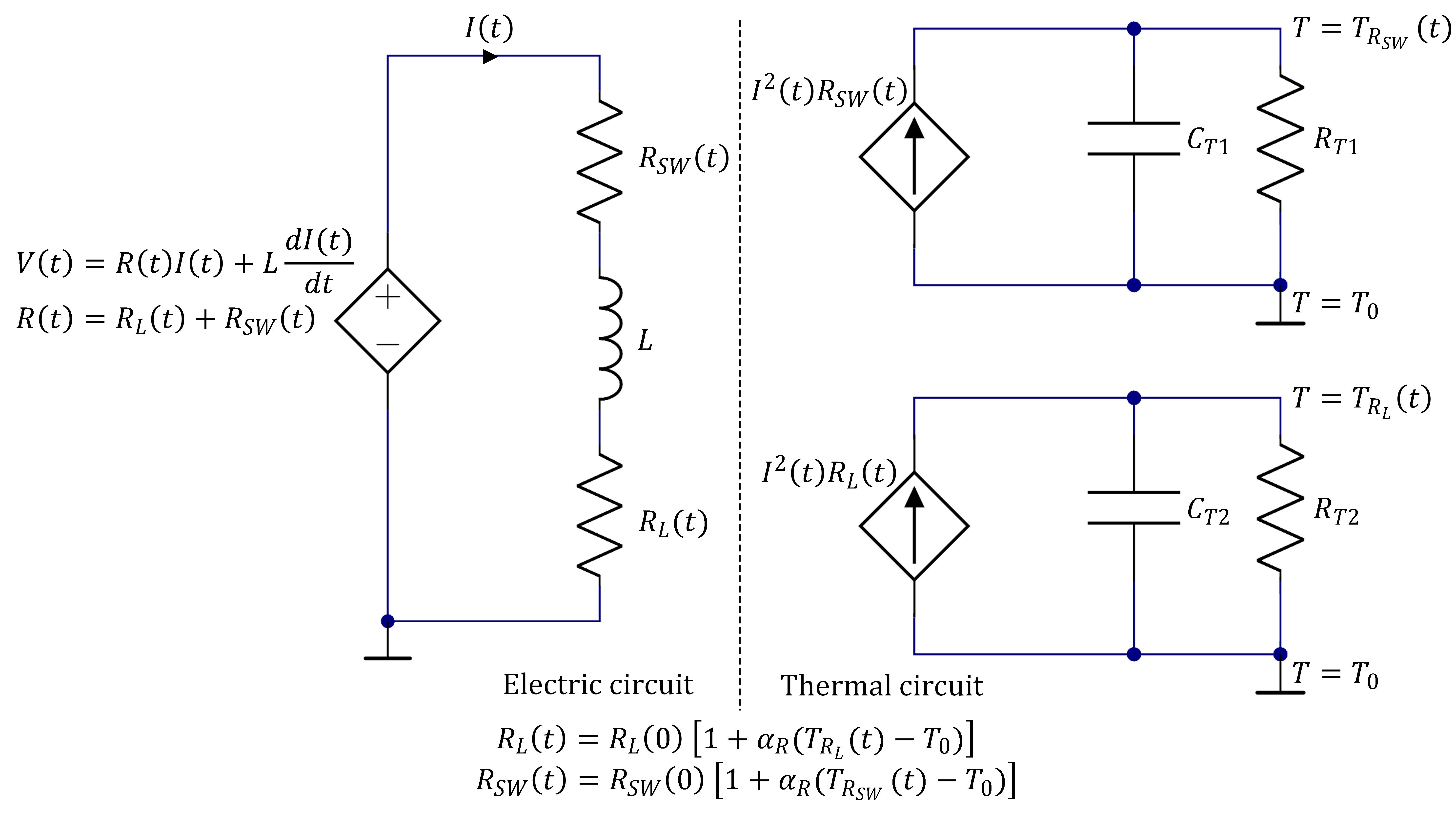
Figure 1. The total system model that is separated by the electrical and thermal parts. All temperatures given are effective temperatures stemming from the lumped model.
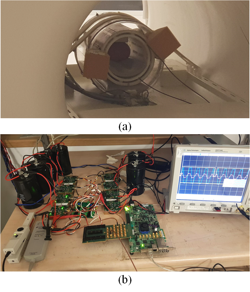
Figure 2. Experiment setup. (a) The readout gradient coil, RF coil, and the phantom inside the MRI scanner. To decrease vibration-based artifacts, dampening with soft material is performed. (b) The amplifier and FPGA setup that drives the readout coil. Current waveforms are measured with a current probe, while voltage waveforms are measured with a differential probe.
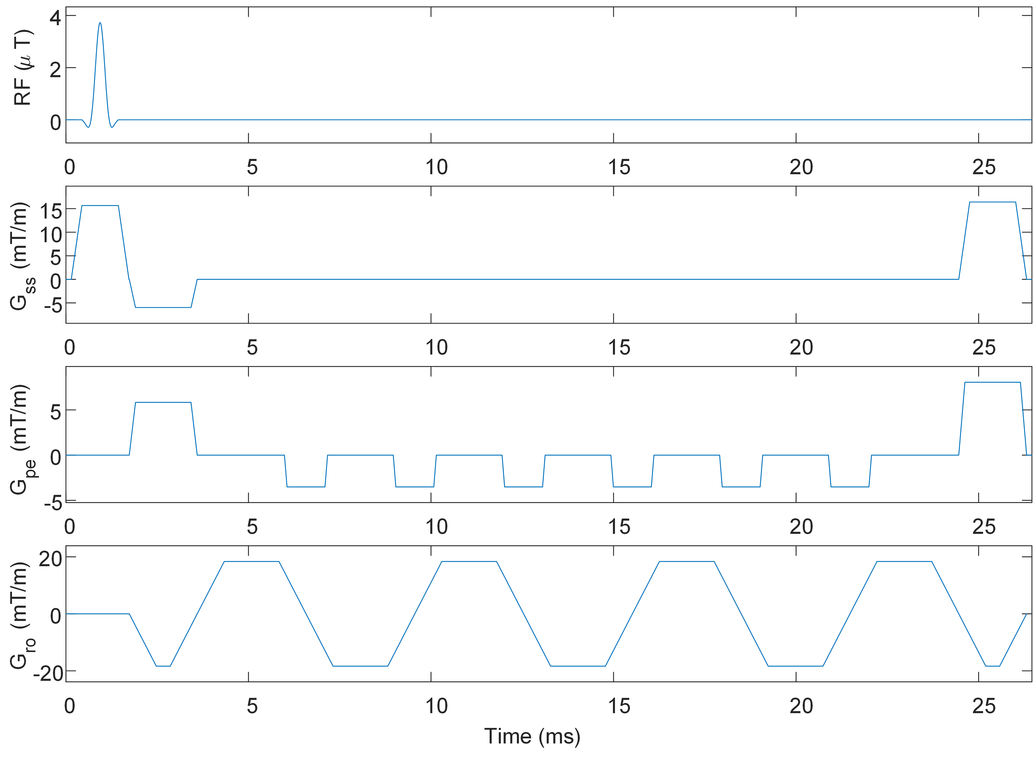
Figure 3. Part of a single TR for a single slice of the multi-shot EPI pulse sequence used for imaging. Matrix: 176x175; resolution: 0.86x0.86 mm2; FOV:150mm; slices: 6; slice spacing: 9mm; slice thickness: 6mm; flip angle: 16°; TR: 150ms; TE: 13ms; echo spacing: 3ms.
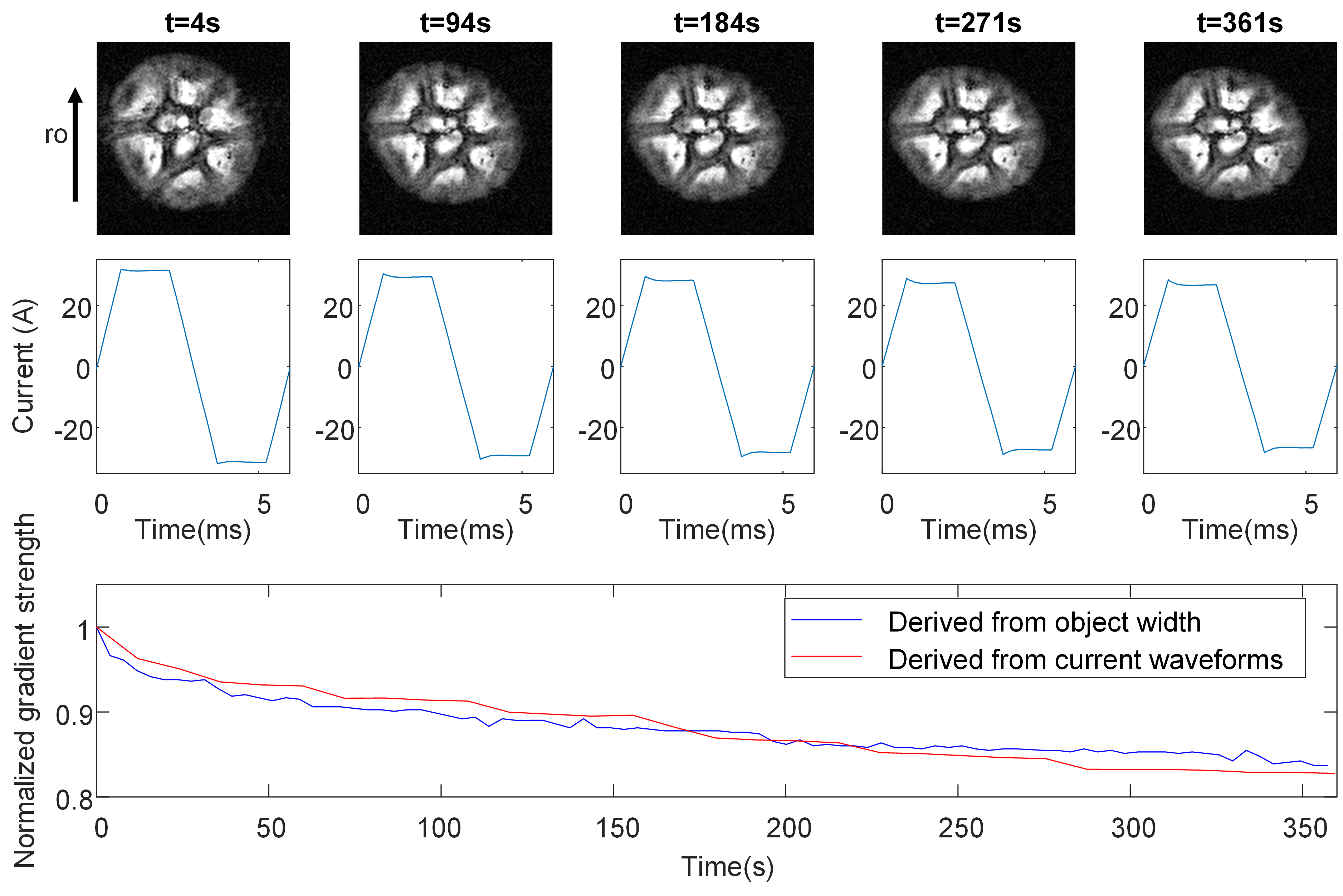
Figure 4. MR results without resistance prediction. Images and current waveforms by 90 seconds apart. The object width is derived from the total pixel count in the readout direction over some threshold.
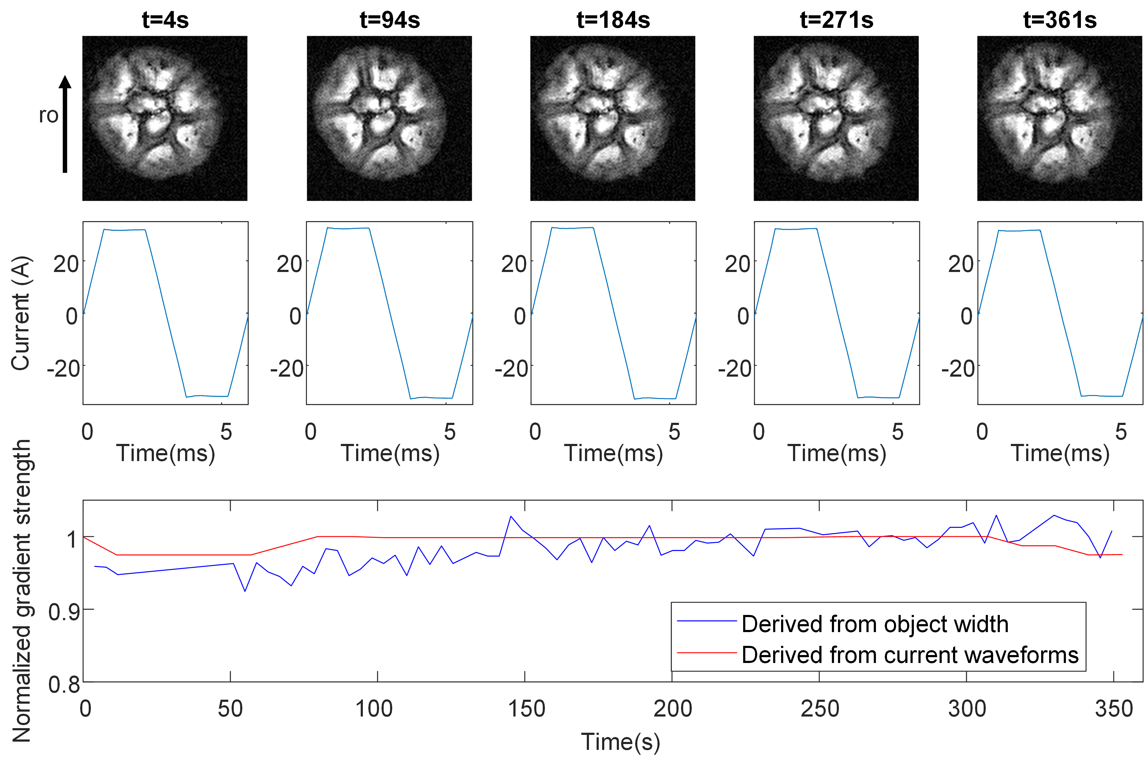
Figure 5. MR results with resistance prediction. Images and current waveforms by 90 seconds apart. The object width is derived from the total pixel count in the readout direction over some threshold.