4566
Analytical expression for gradient eddy current-induced power dissipation in a thin conductive shell: A model for RF shield heating1GE Global Research, Niskayuna, NY, United States, 2Mayo Clinic, Rochester, MN, United States
Synopsis
Keywords: Gradients, Gradients, eddy current
Gradient-induced eddy current in an RF shield can cause significant temperature increase in the patient bore. As gradient coils produce higher amplitudes with faster rise time, understanding and controlling eddy-current heating become more and more important for patient safety and device longevity. Through time-domain analysis, we have derived a mathematical formula that relates the eddy-current heating of a uniform conductive shell to the properties of the conductor and the mean-square slew rate of the gradient waveform. The theoretical prediction was tested by experiments performed on a high-performance head-only gradient (MAGNUS) system.Introduction
MRI scanners typically employ a thin cylindrical metallic shell on the inside of the gradient coil to provide radio-frequency (RF) shielding of the transmit and receive RF coils from the external environment. Because of its proximity to gradient coil wires, an RF shield can be subject to substantial eddy current and heating during imaging, which can potentially pose a patient safety risk and thereby limit the allowable gradient duty cycle. Despite much interest and progress in empirical methods to mitigate heating [1-4], systematic analytical investigation to predict heating in terms of engineering and pulse sequence parameters has not been widely published. In this work we present an analytical derivation of the shield heating equation and provide experimental evidence to support the theory.Theory
The surface-normal magnetic field $$$B_\perp$$$ on a thin conductive shell is related to the surface eddy current by Eq. (1) [5]. In the low frequency regime, as is the case for typical RF shields at typical gradient frequencies, self-induced magnetic field can be ignored so that $$$B_\perp$$$ entirely comes from the gradient field. In this case, the temporal and spatial dependences of $$$B_\perp$$$ can be separated into the gradient waveform G(t) and gradient-normalized magnetic field br (Eq. 2). The stream function T [6] for surface eddy current can be formally solved for as Eq. (4) through solution F of the Poisson-like equation Eq. (3). This leads to Eq. (5) for the instantaneous Joule heating power density. Finally, the time-averaged and spatially integrated power $$$\bar{P}$$$ is given by Eq. (6), which is proportional to the surface conductivity of the shield and the mean-square slew rate of the gradient waveform. The solution F is determined by the gradient design and location of the shield. Figure 2(a) summarizes the computational workflow. A representative power density map is shown in Fig. 2(b). In the following sections, spatial dependence of P and shield conductivity dependence of $$$\bar{P}$$$ are examined experimentally.Experimental Methods
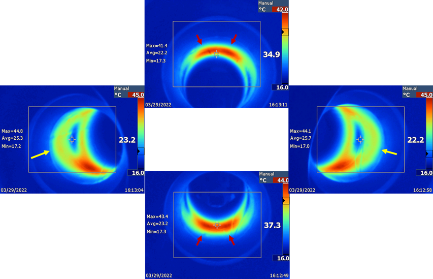
All experiments were performed in a high-performance head-only gradient coil (MAGNUS) integrated in a clinical 3T magnet [7]. The scanner features an insertable RF shield that is made of a stainless-steel mesh and wound on a 41 cm outer-diameter composite plastic tube. Two RF shields were tested that were made of mesh materials provided by two vendors: Belleville Wire Cloth Company, NJ, USA (shield 1, high conductivity), and TWP, CA, USA (shield 2, low conductivity). The surface conductivity ratio, estimated from sample resistance measurement, was 3.8. The temperature of the inner surface of the RF shield cylinder was measured by both fiber-optic temperature sensors (Neoptix, Omni Module, Canada) and a thermal camera (Ti25, Fluke, WA, USA). A modified EPI sequence where the flat-top portion was reduced to near zero (i.e., aggressive ramp sampling during the EPI readout) was used to energize the gradient coil and induce eddy current in the RF shield. Readout directions in both L/R (x) and A/P (y) were used with nominal maximum gradient amplitude Gmax = 74 mT/m and echo spacing = 308 μs.Results
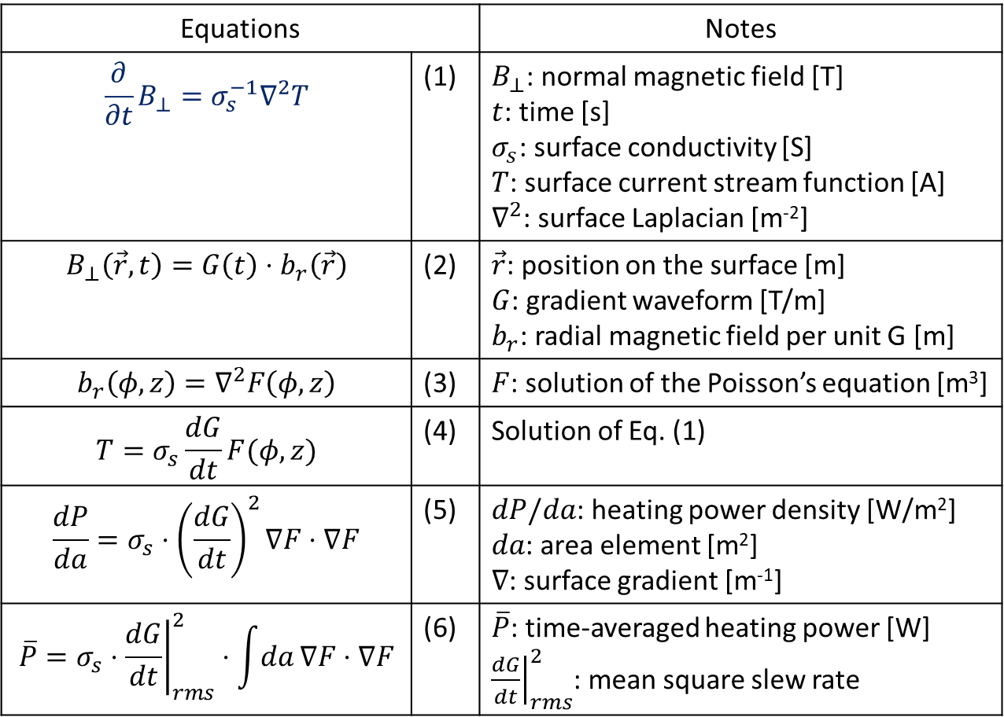
Temperature map. Figure 2(b) shows the power density map, on the z-φ plane, calculated from the x gradient coil of a compact asymmetric head gradient coil that has a similar design as the MAGNUS gradient coil. The map shows two pairs of hot spots at φ = 90° and 270°, corresponding to the top and bottom of the shield cylinder. Additionally, there are two warm regions protruding into the patient end (z < 0) of the cylinder on the left and right sides (φ = 0°, 180°). These features were nicely reproduced in experimental thermal camera data (Fig. 3).Shield dependence. Figure 4(a) shows the temperature time courses at two measurement locations (Fig. 4(b)) with two different shields. The EPI readout direction alternated between L/R and A/P, with a break time in between. The initial temperature rise was markedly different between the two shields. The ratio of the 2-min slopes (indicated by short horizontal bars) was 2.6, when averaged between L/R and A/P directions.
Discussion and Conclusion
In this work we have presented analytical derivation of the eddy current heating equation of a uniform cylindrical RF shield. The method neglects the following important factors: heat diffusion within the shield, cooling by air convection, non-uniformity of the shield such as at solder joints, and anisotropic conductivity of the wire mesh. By assuming a uniform cylindrical shield, we have also neglected cases where the shield is made of several disjoint patches of conductors [4]. Despite these limitations, the experimental data agreed reasonably well with the general prediction of the theory in terms of hot spot locations and shield conductivity dependence of the temperature rise. Our results could help guide optimization of RF shield construction to minimize heating in high-performance gradient systems.Acknowledgements
This work was supported by CDMRP W81XWH-16-2-0054 and NIH U01EB026976. This presentation does not necessarily represent the official views of funding agencies.References
[1] M. Alecci and P. Jezzard, Characterization and reduction of gradient-induced eddy currents in the RF shield of a TEM resonator, MRM 48:404-407 (2002)
[2] M.H. Chishti et al., Design of flanged RF shield for mitigation of RF and gradient coil interactions, 22nd Annual Meeting of ISMRM, Abstract 1293 (2014).
[3] Y. Hua et al., Evaluation of RF shielding effectiveness by method of moments, 26th Annual Meeting of ISMRM, Abstract 4407 (2018)
[4] B.J. Lee et al., Low eddy current RF shielding enclosure designs for 3T MR applications, MRM 79:1745-1752 (2018)
[5] S.-K. Lee et al., Analytical approach towards time-dependent gradient eddy current calculation in cylindrical geometry, ESMRMB 2012, Program #286
[6] S.-K. Lee and J. Schenck, Analytical approach to calculate idealized surface current for a shielded magnetic field coil in a separable coordinate system, TechRxiv. https://doi.org/10.36227/techrxiv.20057135.v1
[7] T.K.F. Foo et al., Highly efficient head-only magnetic field insert gradient coil for achieving simultaneous high gradient amplitude and slew rate at 3.0T (MAGNUS) for brain microstructure imaging, MRM 83:2356-2369 (2020)
Figures