4563
RF Pulse Predistortion for Low-Field MRI Based on Spin Physics Using a Neural Network Amplifier-to-Bloch Equation Model1Biomedical Engineering, Vanderbilt University, Nashville, TN, United States
Synopsis
Keywords: RF Pulse Design & Fields, Low-Field MRI, Amplifiers, Predisortion
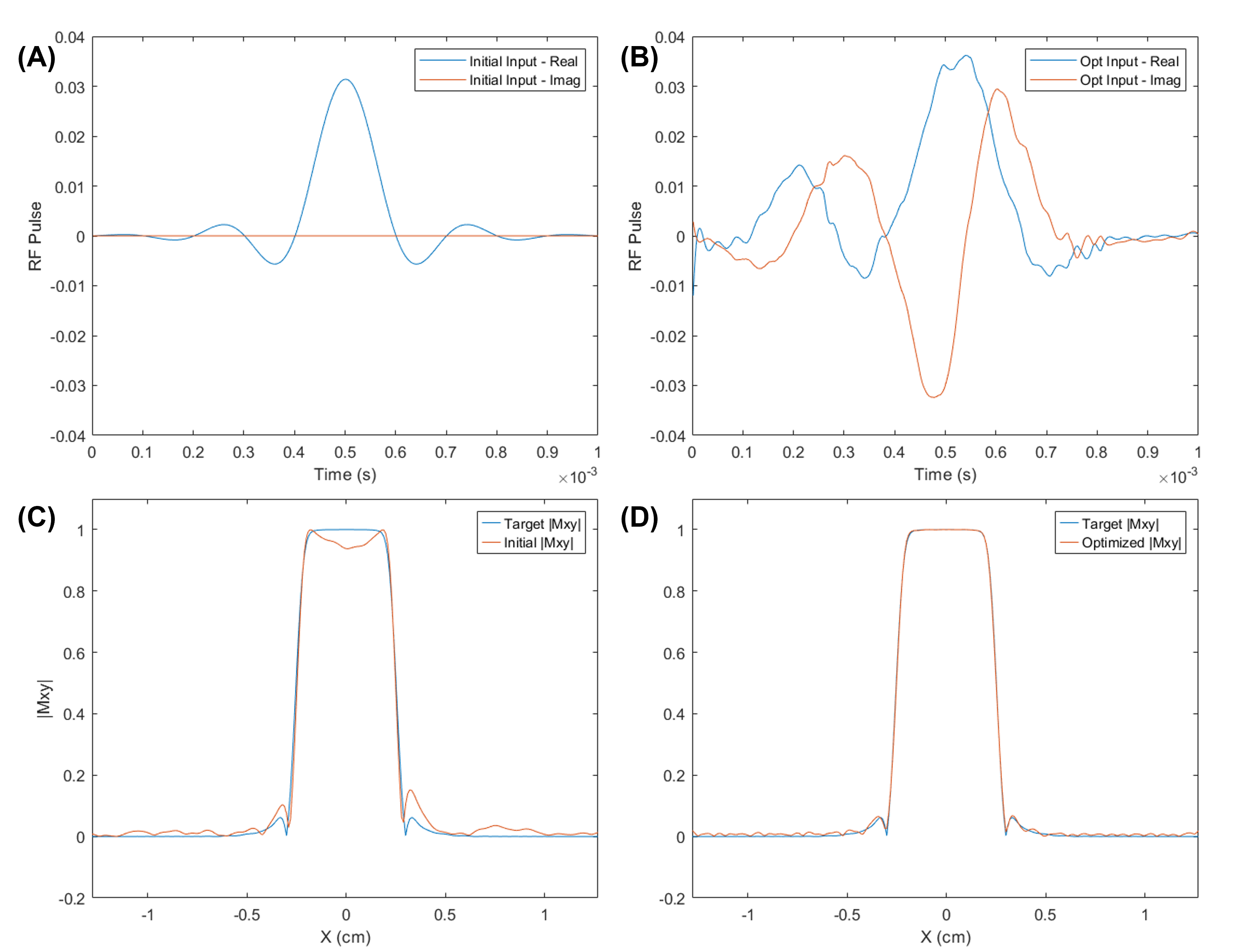
In low-field MR, low-cost amplifiers with reduced fidelity are used. Current solutions to this problem require additional hardware and do not optimize the pulse for the final excitation profile. The proposed methodology models the amplifier with a neural network, connects the network to a Bloch simulator, and optimizes the pulses for the desired excitation profile. In simulation, a windowed sinc pulse (time-bandwidth product = 10, phase = 0 radians, duration = 1 ms) was optimized to minimize the loss between the target profile and the generated profile after the pulse passes through the amplifier to 0.05% of the starting loss.
Introduction
The recent push towards low-field MR addresses the problems to accessibility due to the high cost and lack of portability of MR. In particular, considerable effort is devoted to replacing costly MRI components with lower-cost components whose lower performance can be compensated by less expensive computation.1 A scanner’s power RF amplifiers are an expensive component that can be replaced with lower cost amplifiers that have fewer stages but have reduced fidelity. The distortions introduced to RF pulses by these amplifiers change the excitation profile of the original pulse, decreasing image quality. Current solutions to this problem include using a receiver channel to correct the output through feedback in real time,2 using a sensor on the coil to measure and iteratively correct the output,3 and iteratively adding corrective subpulses.4 Drawbacks of these solutions include their requirement of additional hardware and the fact that they do not optimize for the excitation profile which ultimately determines image quality, but rather focus on achieving a specific output pulse shape which may not be possible to generate with a given amplifier + transmit/receive switch + RF coil combination. Our proposed solution is to instead model the amplifier with a neural network trained by loop back measurements, connect that network to the Bloch equation to calculate the final excitation profile, and then optimize input pulses for a desired excitation profile. This methodology requires no additional hardware once the network is trained, specifically targets improved imaging quality, and can be easily applied to any pulse before scanning.Methods
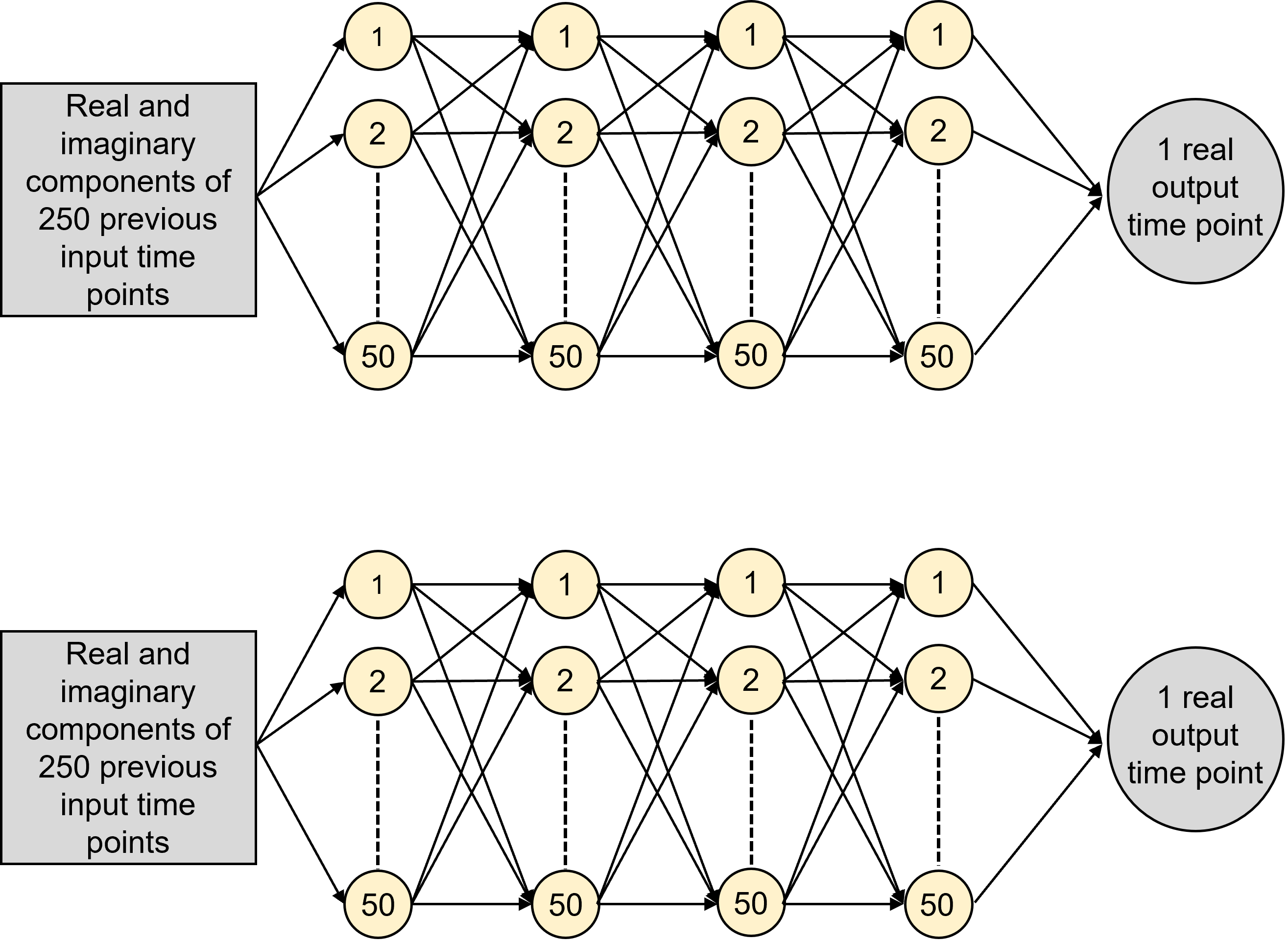
A dataset of 7200 windowed sinc pulses was generated with varying phases between 0 and 7π/4, time-bandwidth products between 2 and 10, and durations between 1 and 10 ms. Input and output pulses to the amplifier were recorded at 2 MHz (47.5 mT) with a 2 μs dwell time using a 20W Henry radio 20B amplifier driven by a Medusa spectrometer.5 The output pulse from the amplifier was recorded by looping the pulse back to the Medusa receive channel after passing the pulse through a 6dB attenuator to prevent receive overranging (Figure 1).The input/output pulse pairs were separated into equally sized training, evaluating, and testing datasets. Two model structures were trained, tuned, and compared in Julia using the Flux.jl package. The first was a fully connected model using 250 previous complex-valued time points (0.5 ms) as input to predict each output time point. The second was an recursive neural network connecting an LSTM cell to a 100-node layer. Two models were trained when comparing structure, one to predict the real components of the output pulse and one to predict the imaginary components.
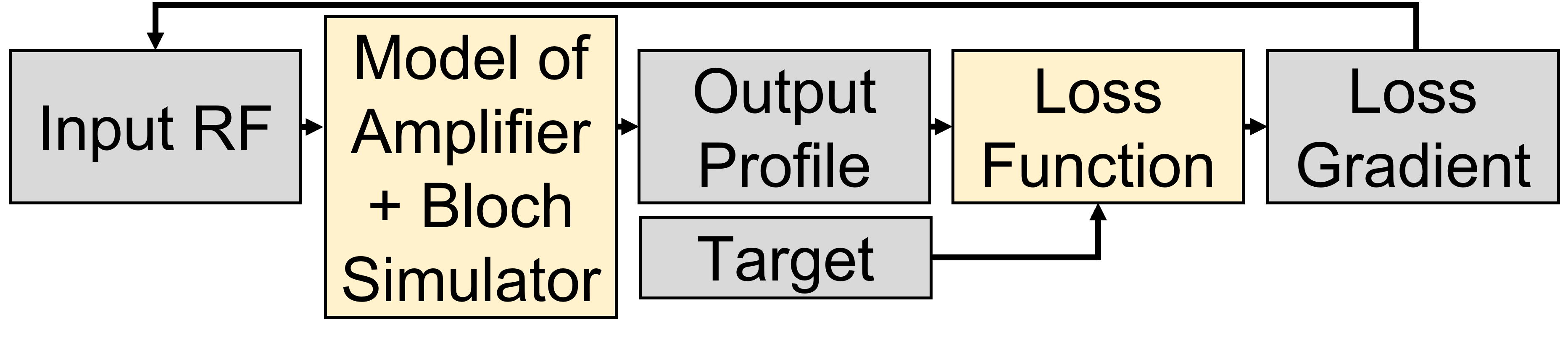
After selecting the model with the highest accuracy, a differentiable Bloch equation simulator was appended to the neural network. A gradient descent algorithm was implemented to optimize the input pulse for this target excitation profile by iteratively correcting the input pulse based on the gradient of the loss function, which takes the mean square error between the excitation profile of the pulse after passing through the amplifier model and the target profile (Figure 2). This end-to-end optimization through both the neural network model of the amplifier and the Bloch equation simulator allows for the input pulse to be corrected before scanning to achieve a desired excitation profile.
Results
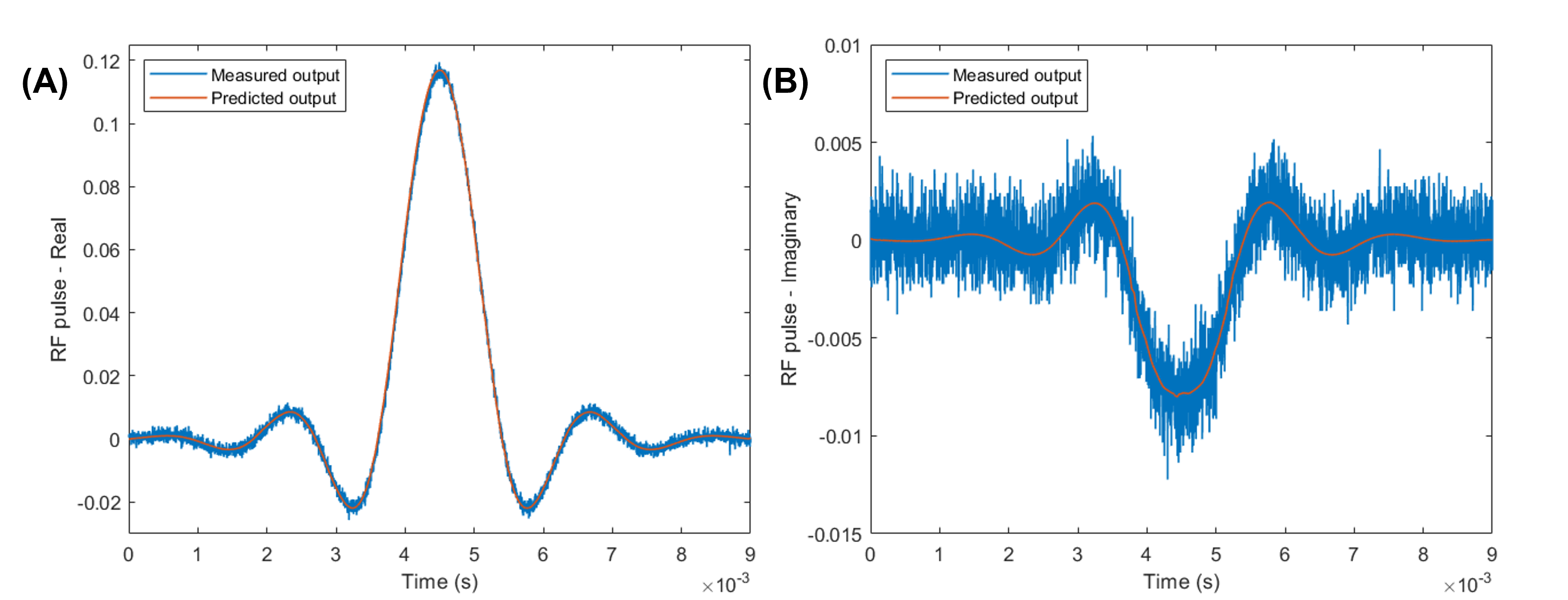
The neural network with the highest accuracy was the fully connected model using four layers with 50 node each connected by ReLu functions (Figure 3). Sample model predictions for the real and imaginary components of the output of a windowed sinc pulse (time-bandwidth product = 10, phase = 5π/4 radians, duration = 9 ms) are shown in Figure 4. The neural network model of the amplifier was able to accurately predict the shape of the output RF pulse even with the noise in the sample pulse.This model was then used to predict the output pulse from the amplifier during optimization. The simulated results of the optimization of a windowed sinc pulse (time-bandwidth product = 10, phase = 0 radians, duration = 1 ms) is shown in Figure 5. After passing through the amplifier, the original pulse (A) generates a distorted excitation profile (C). The optimization code effectively compensates for these distortions. When passing in the predistorted pulse (B) to the amplifier, the loss between the generated excitation profile (D) and the target profile was 0.05% of the starting loss.
Conclusions
We successfully created a neural network-based amplifier model that can accurately predict the output RF pulse given an input pulse, and we can use this model to improve the excitation profile generated by the pulse in simulation by optimizing the input pulse to the amplifier through a gradient descent algorithm. Unlike the existing methodology to compensate for distortions introduced to RF pulses by amplifiers in low-field MR, this methodology is cost effective, guarantees an improved excitation profile, and thereby improved image quality, and can be easily applied to any pulse during pulse design. The next step in this work is to validate the methodology by imaging the profiles of the optimized pulses compared to the original pulses on a 47.5 mT MRI scanner.Acknowledgements
This project was supported by the Vanderbilt University Summer Research Program Littlejohn Award and NIH grant R01 EB030414.References
[1] Marques J, Simonis F, Webb A. Low-Field MRI: An MR Physics Perspective. Journal of Magnetic Resonance Imaging. 2019;49:1528-1542.
[2] Zanchi M, Stang P, Kerr A, et al. Frequency-Offset Cartesian Feedback for MRI Power Amplifier Linearization. IEEE Transactions on Medical Imaging. 2011;30:512-522.
[3] Stang P, Kerr A, Pauly J, et al. An Extensible Transmit Array System Using Vector Modulation and Measurement. In Proceedings 16th Scientific Meeting, International Society for Magnetic Resonance in Medicine, Toronto, page 145, 2008.
[4] Ha Y, Selvaganesan K, Wu B, et al. Practical Method for RF Pulse Distortion Compensation Using Multiple Square Pulses for Low-Field MRI. PLOS One. 2022;17.
[5] P. P. Stang, S. M. Conolly, J. M. Santos, J. M. Pauly, and G. C. Scott. Medusa: A scalable MR console using USB. IEEE Transactions on Medical Imaging, 31(2):370–379, 2012.
Figures