4560
Falling conductive loop: A simple analytical model for magnetic damping
Seung-Kyun Lee1
1GE Global Research, Niskayuna, NY, United States
1GE Global Research, Niskayuna, NY, United States
Synopsis
Keywords: Magnets (B0), Magnets (B0), magnetic damping
The motion of a conductive object is profoundly affected by the presence of a strong magnetic field. A conductive loop falling inside an MRI magnet can serve as an analytically solvable model to explore magnetic damping. We present a pair of magneto-mechanical coupled equations to describe its motion and verify their solution with experimental data. A simple formula for the loop's falling time was obtained, which indicates that magnetic damping is proportional to B02.Introduction
It has been suggested that magnetic damping may substantially reduce vibration of conductive materials in high-field MRI [1-3]. While magnetic damping and stiffening are familiar phenomena to anyone who tried to move a metal in a clinical MRI magnet, the exact mechanism of magnetic disturbance of mechanical motion has rarely been articulated in the MRI literature. There are, for example, differing views on how magnetic damping scales with B0, i.e., linearly [1] vs. quadratically [2]. Here, a simple magneto-mechanical coupled system, a conductive loop falling on the table of an MRI magnet, is presented as a model to demonstrate the interplay between mechanical (angular displacement θ) and electromagnetic (current I) degrees of freedom. An analytical expression for the fall time illustrates B02 dependence of magnetic damping which is experimentally verified.Theory
System description. Consider an electrically conductive and flat, single-turn closed loop whose plane can rotate freely about an axis (x-axis) on the horizontal (zx) plane under a uniform static magnetic field B0 (Fig. 1). The loop has an area A, resistance R, inductance L, and number of turns N = 1. Mechanically it is part of a flat rigid body (e.g. frame) whose total mass and moment of inertia are m and Ii, respectively. The body's center of mass is at distance r from the x-axis. This system has two degrees of freedom: rotation angle θ and electric current I (Fig. 1).Coupled equations. If the loop is let go at an initial angle θ0, its gravitational fall will incur time-varying magnetic flux which induces eddy current that slows down the fall via the Lorentz force. This is captured by Eqs.(1-2): Eq.(1) describes angular acceleration under gravitational and magnetic torque, while Eq.(2) describes the Kirchhoff's voltage law with motion-induced electromotive force. Eqs.(3ab) define the initial condition. Eqs.(1-3) can be numerically solved for I(t) and θ(t). If N > 1, A, R, L will scale as AN, RN, LN2, while m will increase linearly with an additive constant (mass of the frame).
Approximate solution. An approximate solution Eq.(4) can be found in the overdamped case where d2θ/dt2 and dI/dt can be neglected. Eq.(4) predicts that the loop will hit the ground (θ=90deg) at the fall time Eq. (5) provided θ0 << 1. Eqs.(4-5) turn out to be a remarkably good solution for a wide range of parameters. Figure 3 shows a representative case where cosθ is almost exactly linear in time, in accordance with Eq.(4). Comparing Eq.(4) with the velocity of an overdamped linear motion (v = F/b, b: damping coefficient), we identify (AB0)2/R as the magnetic damping coefficient.
Experimental Methods
Circular loops with 11.9 cm diameter and N = 2,4,6,8 were wound from an 18-gauge (AWG) copper wire and electrically closed by soldering. Each loop was glued to the lid of a DVD jewel case which was hinged onto its base with low friction. The base was taped to a 3T MRI table (Fig. 4). After moving the table to a desired position, the lid and the loop were released from a near-vertical position (θ0 ~10deg) and the time for touchdown was measured by a stopwatch. The experiment was repeated at multiple positions for N = 8, and at the isocenter for each N. The measured times were compared with the theoretical fall time Eq. (5) based on the measured weight mg of each lid (+loop) and calculated resistance R of the wire. The static field at different locations was estimated from the vendor-supplied electromagnetic design of the magnet.Results
Figure 5(a) shows that the measured fall times at the isocenter almost exactly match the theoretical formula, with errors less than 2%. Small uncertainties in estimation of the center of mass, area of the loop, and electrical resistance at the solder joint could be sources of the error. This result strongly supports our theoretical formulation Eqs.(1-2) and the overdamped solution Eq.(5). The B0 dependence is illustrated in Fig. 5(b) where the measured times agree well with theory in regions of homogeneous B0 but fall short in the transition region near the bore entrance. The discrepancy is likely because large B0 gradient creates nonzero net force in the loop, in addition to magnetic torque, which was ignored in Eq.(1). The inset shows that the fall time data follow much more closely the magnet's B02 profile than B0, providing strong support of B02 dependence of magnetic damping.Discussions and Conclusion
Dramatic slowdown of a falling conductor has been a popular item of demonstration to illustrate the power of an MRI magnet. In this work we have attempted to elucidate its mechanism in terms of motion-induced eddy current and magnetic torque acting as a damping force. Our theory was well supported by experimental data and helps identify factors that govern magnetic damping. In particular, the measured fall times inside and outside of a 3T magnet strongly favored B02 dependence of magnetic damping. The presented model can provide a benchmark for future research on magneto-mechanical coupling in MR engineering.Acknowledgements
No acknowledgement found.References
[1] N. Boulant et al., Vibration measurements of the SC72 gradient versus field strength in the Iseult magnet, ISMRM 2022, Abstract 1371
[2] S. Winkler et al., On the accurate analysis of vibroacoustics in head insert gradient coils, MRM 78:1635-1645 (2017)
[3] L. Jiang, T.J. Havens, Environmental vibration induced magnetic field disturbance in MRI magnet, IEEE Trans Appl Supercond. 22(3), 4400704 (2012)
Figures
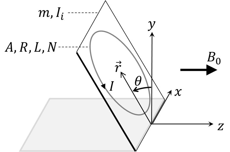
Figure 1. Schematic diagram of a falling conductive loop with a single turn (N =
1). The loop is attached to a rectangular hinged frame which is non-conductive.
The static magnetic field B0 is assumed uniform. The loop has an area A,
resistance R, and self-inductance L. The loop and the frame have total mass m
centered at r, and moment of inertia Ii with respect to the hinge.

Figure 2. (a) Coupled magneto-mechanical equations (Eqs. (1-2)) and initial
conditions (Eq. (3)) for the current I(t) and angle θ(t) of the falling
conductive loop. (b) Approximate solution for the time evolution of the
vertical height (y/r = cosθ) of the center of mass. (c)
Approximate solution for the fall-to-the-ground (touchdown) time from Eq. (4),
assuming small initial angle (θ0 << 1).
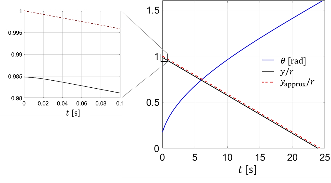
Figure 3. Representative numerical solution for the time-dependent angle
(θ(t)) and height (y(t)/r) of the coupled equations Eqs. (1-2) compared
with the approximate solution (yapprox/r) from Eq. (4). The zoomed
inset shows a brief period of initial nonlinear evolution of y(t) that quickly
settles into a linear decline.
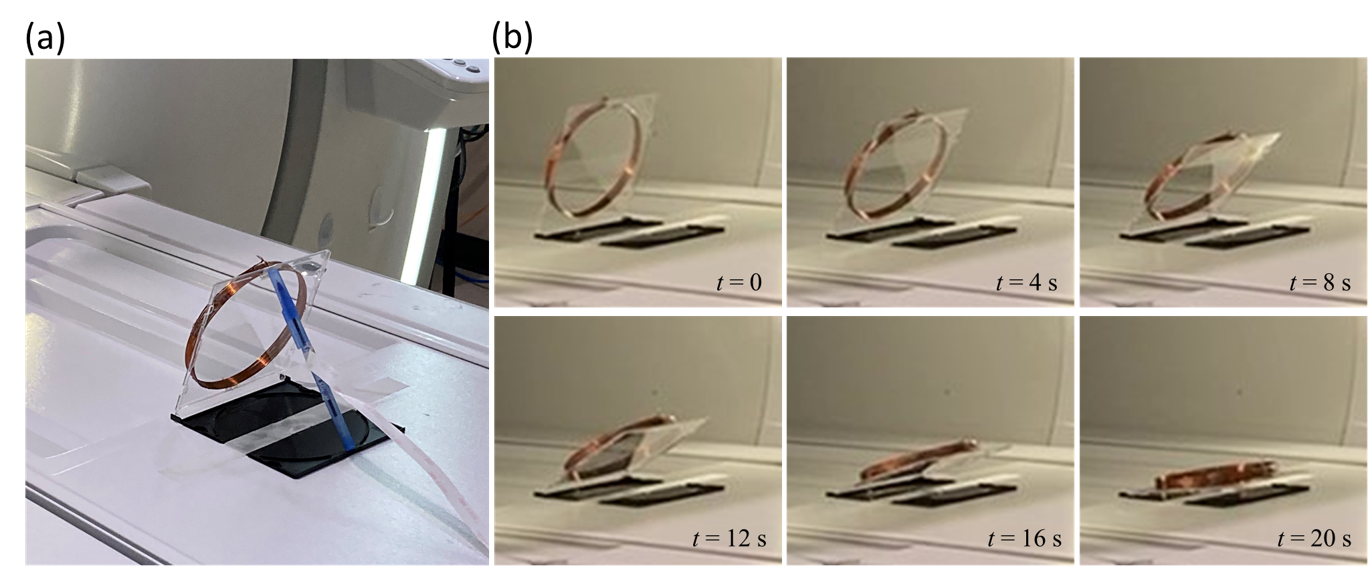
Figure 4. Picture of the experimental setup (a)
and representative frames of a recorded video (b). The lid of the DVD jacket
falls under the influence of gravity and magnetic damping when the plastic
support rod (blue pen) is removed. Countdown to touchdown was manually done
with repeatability of about 0.2 s.
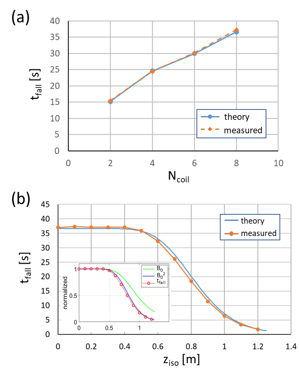
Figure 5. (a) Measured fall times for different DVD jackets with varying N = Ncoil = 2~8 compared with theoretical prediction. (b) Measured fall times for an N = 8 setup as a function of the z location on the table of a clinical 3T MRI
scanner. Blue solid line indicates theoretical prediction based on the magnet’s
B0 map ignoring B0 inhomogeneity. The inset compares B0 and B02
profiles with the fall time data, all normalized to the values at the
isocenter.
DOI: https://doi.org/10.58530/2023/4560