4559
Developing an In-Bore MRI-Compatible Syringe Pump
Martin D Holland1, Seth N Lee2, and Harrison D Kim2
1Interdisciplinary Engineering, University of Alabama at Birmingham, Birmingham, AL, United States, 2Radiology, University of Alabama at Birmingham, Birmingham, AL, United States
1Interdisciplinary Engineering, University of Alabama at Birmingham, Birmingham, AL, United States, 2Radiology, University of Alabama at Birmingham, Birmingham, AL, United States
Synopsis
Keywords: New Devices, New Devices, Syringe pump, MRI Compatibility, 3D Printing
Delivering a contrast (or therapeutic) agent to a subject inside an MRI bore requires an expensive electronically programmed syringe pump and a long tube filled with the agent. We developed an inexpensive 3D-printed MRI-compatible syringe pump that can be used inside an MRI bore. This syringe pump yields a highly reproducible infusion rate, which can be readily adjusted using gears with different gear ratios.Introduction
An electrically powered syringe pump is conventionally used to deliver a contrast (or therapeutic) agent to a subject during an MRI scan. However, MRI-compatible electronically programmable syringe pumps are expensive. Also, non-MRI compatible syringe pumps must be placed outside the MRI room, requiring long tubes (typically 10-15 m long) filled with the agent. Thus, we developed a 3D-printed MRI-compatible syringe pump that can be placed inside MRI bore together with a subject.Method
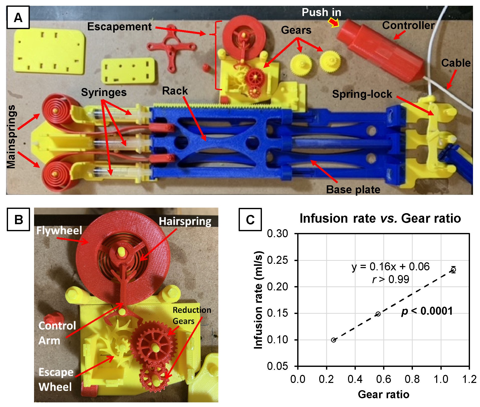
The syringe pump was designed using the computer-aided design (CAD) software SolidWorks (SolidWorks Co., Dassault Systèmes, Waltham, MA) and fabricated using a 3D printer (Raise3D Pr02, Raise 3D Technologies, Inc., Costa Mesa, CA). Figure 1A shows a photograph of the syringe pump comprising a base plate, a rack, a syringe cradle, two mainsprings, a spring lock, a control cable, and an escapement. The base plate provides rigid support for the other components and locations for those components to connect, slide, or rotate. The rack transmits the power of the mainsprings to the escapement and the syringes. The rack has teeth on one side that mesh with and power the escapement. The syringe cradle holds the barrels of three syringes. The mainsprings are mirror-image spiral springs that attach between the base plate and the front end of the rack. The spiral shape was chosen as it provides a more-constant force than typical helical springs, and it takes up less room. The spring lock is a small, spring-loaded clip that is rigidly attached to the base and clips onto the back end of the rack. It ensures that the system can be loaded in advance and can hold the mainsprings in position until the device is ready to be used. The control cable is comprised of an outer sleeve and an inner cable. The cable-in-sleeve configuration allows the spring lock to be activated from a distance while allowing the control cable to remain flexible and portable. The controller is a push-button mechanism designed such that when the button is depressed, tension is applied to the control cable. This pulls back on the spring lock, which decouples the spring lock from the rack, allowing the rack to depress the syringes. Figure 1B shows the escapement, a special series of mechanical parts that act together to control the speed of the device and, by extension, the infusion rate from the syringes. The internal components of the escapement are similar to those found in a mechanical clock, including an escape wheel, a control arm, a flywheel, a hairspring, and a set of reduction gears. Different sets of reduction gears can be installed to vary infusion rates. The syringe pump was tested with three 5-mL syringes filled with pure water. Three gears having gear ratios of 1.09, 0.56, and 0.25 were used. Each gear was installed into the escapement, and the syringe pump was run 20 times repeatedly. The output volume of the three syringes and the time taken to deliver the volume were measured via frame-by-frame analysis of the videos recorded in each run. The infusion rate (ml/s) at each gear ratio was calculated and given as mean±SD. The coefficient of variation (COV) of the infusion rate was calculated at each gear ratio. The correlation between the infusion rate and the gear ratio was statistically analyzed.Results
Figure 1C summarizes the test results. Three gears with gear ratios of 1.09, 0.56, and 0.25 produced infusion rates of 0.232±0.006 ml/s, 0.148±0.002 ml/s, and 0.099±0.001 ml/s, respectively. The COVs of three gears with gear ratios of 1.09, 0.56, and 0.25 were 2.56%, 1.37%, and 1.13%, respectively. The infusion rates were significantly correlated with the gear ratios (r>0.99, p<0.0001).Conclusion and Discussion
We developed a 3D-printed MRI-compatible syringe pump yielding high reproducibility. The infusion rate can be readily adjusted by exchanging the gear set. This syringe pump is inexpensive and easier to use, store, and deploy than conventional ones. This device will be located inside the MRI bore, delivering the MRI contrast or therapeutic agent to research subjects such as phantoms, animal models, and, eventually, human subjects.Acknowledgements
This study was supported by the National Cancer Institute, UH3CA232820.References
No reference found.Figures
Figure
1. In-bore MRI-compatible syringe pump.
(A) The MRI-compatible syringe pump can be used inside an MRI. It
is made of 3D-printed parts, including base plate, rack, mainsprings,
escapement, spring lock, and controller. It can hold 3 syringes.
(B) The escapement mechanism. This controls the infusion rate. Made
of the escape wheel, control arm, flywheel, hairspring, and reduction gears.
The reduction gears’ ratio determines the infusion rate.
(C) Infusion rate vs. gear ratio. This graph shows the
correlation between the reduction gear ratio and infusion rate (r >
0.99, p < 0.0001).
DOI: https://doi.org/10.58530/2023/4559