4543
Continuous wave radar for carotid pulse sensing in Magnetic Resonance Imaging1Stanford University, Stanford, CA, United States, 2GE HealthCare, Aurora, OH, United States
Synopsis
Keywords: Hybrid & Novel Systems Technology, Image Reconstruction
Non-contact synchronization MRI with heart motion is still an open challenge. Inaccurate cardiac gating often complicates image reconstruction and leads to poor or non-diagnostic images. Continuous wave doppler radar is a non-contact, noninvasive novel systems technology that could monitor cardiac motions without distortion from the MRI electromagnetic environment while offering an alternative to state-of-the-art (ECG) triggering.Introduction
In cardiac MRI, the electrocardiogram (ECG) is the preferred method for synchronizing cardiac MRI with heart motion and physiological monitoring [1, 2]. The synchronization can be performed either prospectively, via triggering data acquisition from the detection of the QRS complex, or retrospectively, by reordering the continuously acquired data acquisitions. However, the MRI B0 field can distort the ECG waveshape via the magnetohydrodynamic (MHD) effect [3]. Moreover, interference from RF pulses and the gradients also distort the ECG signal. Hence, accurate cardiac image synchronization remains an open challenge for MRI. A non-contact method would be preferred.Many alternative techniques, including photoplethysmogram (PPG), phonocardiogram and doppler ultrasound exist but all have limitations in delay, sensitivity or precision. Pilot tone methods are non-contact but require interoperability with the MRI receive chain [4, 5]. Continuous wave (CW) doppler radar is a non-contact, noninvasive novel technique for monitoring cardiac movements that can operate independent of the scan operations [6–8]. It is not distorted by the MRI electromagnetic environment. Here, we compare a low microwave band (3.2 GHz) and mm-wave band (24 GHz) CW radar to ECG, PPG and a surface coil S21 (simulated pilot tone) to investigate the feasibility of CW doppler radars on a testbench to synchronize cardiac motion and monitor patient physiology for future deployment in MRI.
Methods
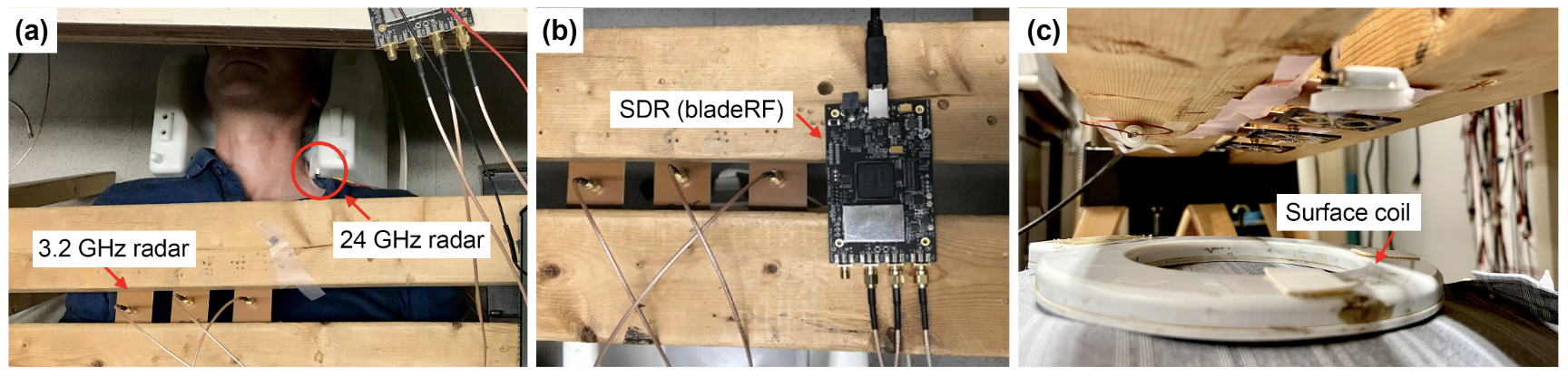
To assess CW radar feasibility, two radar systems were set up (Fig. 1). The 3.2 GHz radar used an SDR (bladeRF2.0, Nuand) with one transmit and two receive channels. The transmit (center) and receive (two sides) antennas were positioned approximately 5 cm above the chest (Fig. 1a). The transmit gain was set to 30x, and the receive gain was set to 40x. The system bandwidth was 200 kHz, and all data were collected during a period of 10 seconds with a 1 MHz sampling rate. The 24 GHz radar used the RFbeam K-LC5. The antenna was positioned next to the left common carotid artery, approximately 1 cm away. All data were collected during a period of 10 seconds with a 10 kHz sampling rate with a Digilent Analog Discovery. The PPG (pulsesensor.com) was positioned at the tip of the index finger using a Velcro strap. Two of the 3-lead ECG electrodes (Sparkfun) were positioned on the left and right arm, respectively, and one electrode was positioned by the left side hip. All data were analyzed using Matlab.Results and Discussion
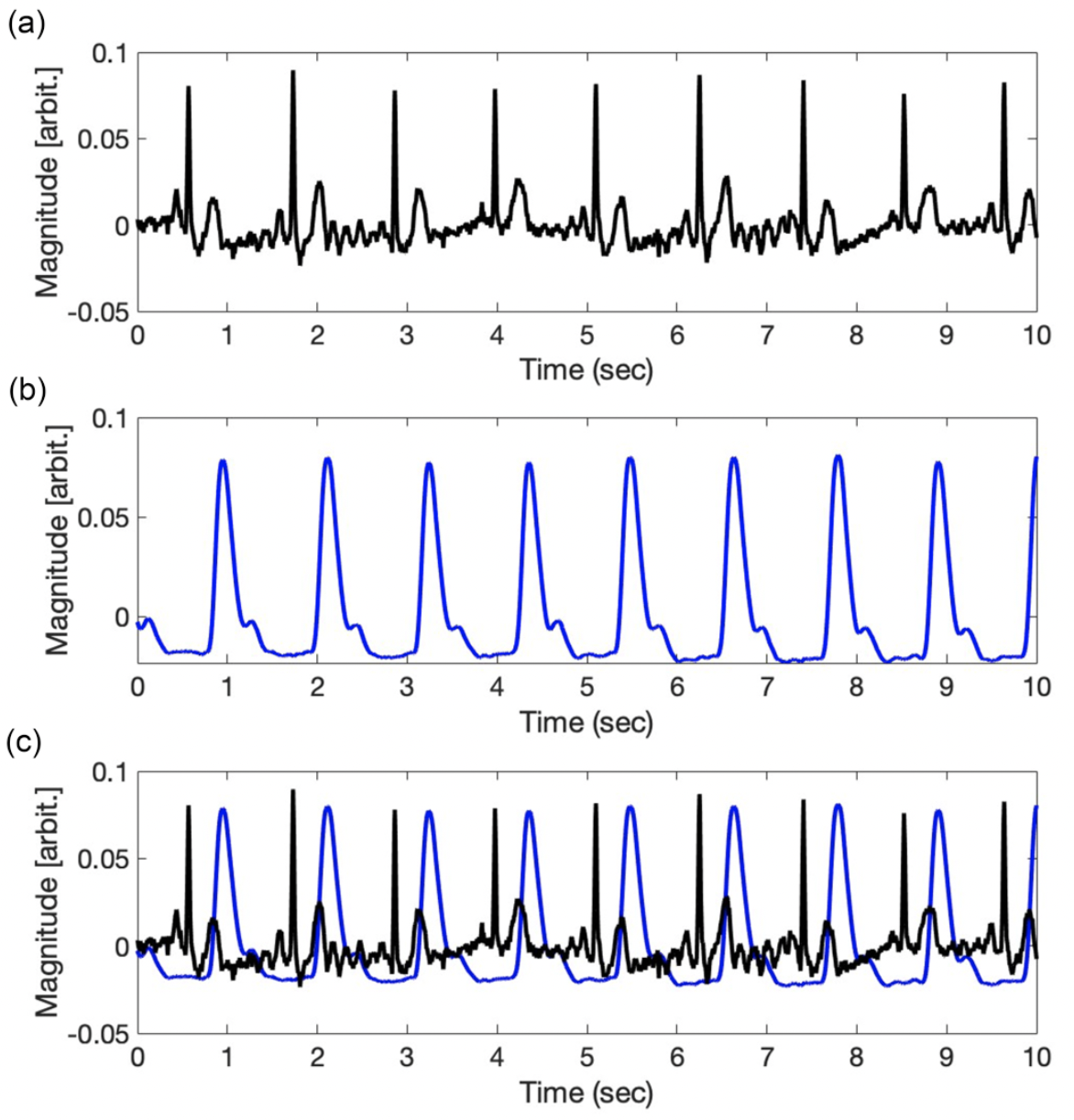
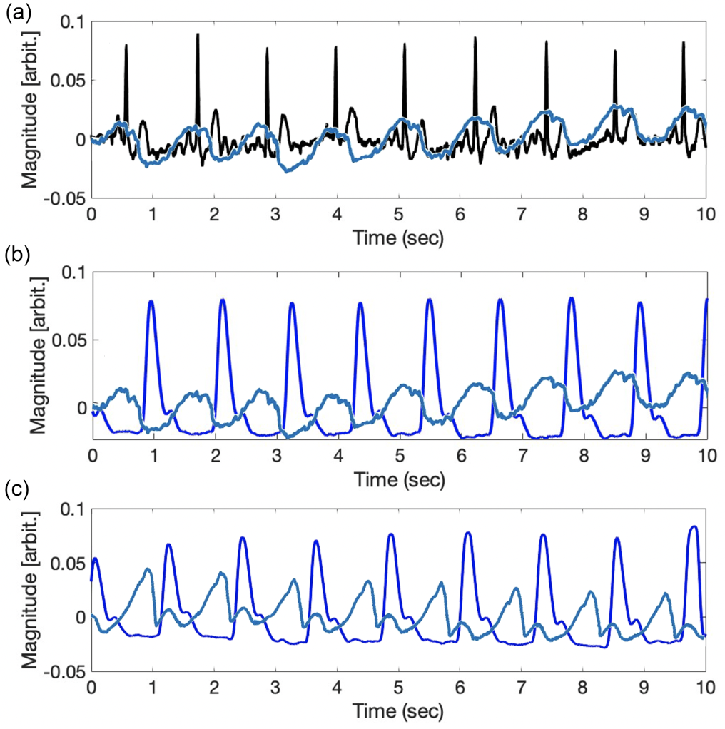
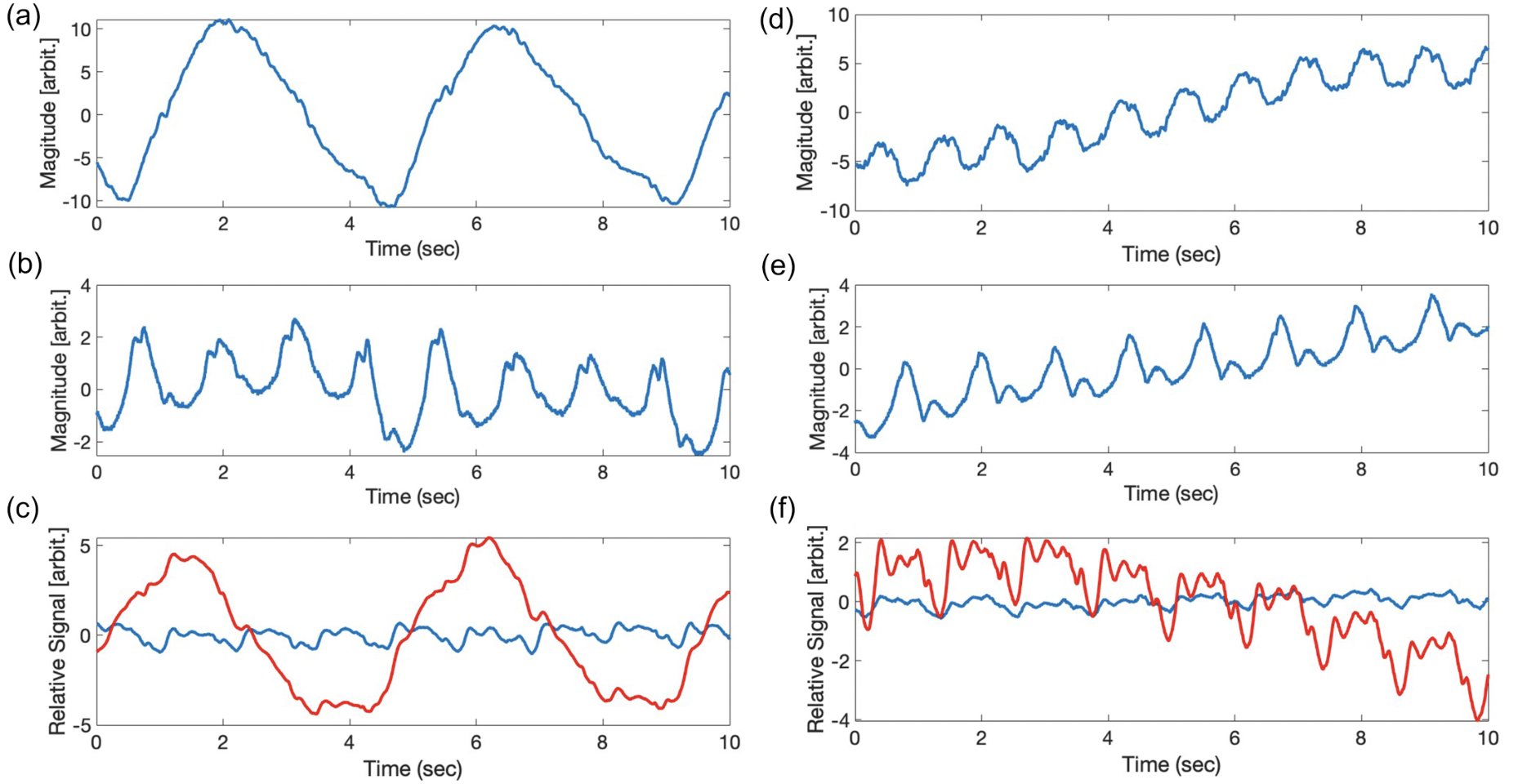
Figure 2 shows the reference signals obtained simultaneously by ECG and PPG—the signal data are not perfectly synchronized. There is approximately 180 ms delay in the PPG peak signal compared to the ECG R-R interval changes, due mostly to the pulse transit time from finger to heart [9]. Hence, PPG is less common in cardiac gating because of signal delays. When we compared the ECG and PPG signals to the simultaneous 3.2 GHz or 24 GHz radar signals, we observed perhaps 30 ms delays in the 3.2 GHz signals with the ECG signal (Fig. 3a). The signal delay between PPG and both radars is approximately 150 ms, similar to the delay between PPG and ECG.We observed breathing and heart motion from the 3.2 GHz and 24 GHz radars and the surface coil. Figures 4a and 4d show the chest and heart signals of the volunteer under free-breathing. Since the 3.2 GHz antennas were positioned right above the chest, they pick up the surface chest motion from inhalation/exhalation (Fig. 4a). When the 24 GHz radar is positioned right next to the left common carotid artery, it picks up mostly the pulse signal from the carotid artery instead of the chest motion from free-breathing. When the volunteer holds their breath, both the 3.2 GHz and 24 GHz radar pick up only pulse signals. Figure 4b shows the heart motion detected from chest surface movement, and Figure 4e shows the pulse from the carotid artery. Besides the two radars, we also observed breathing and heart motion from loading changes in surface coil S21, which mimics pilot tone operation. Figure 4c shows both the breathing and heart motion of the volunteer during free-breathing, and figure 4f shows the heart motion of the volunteer during breath-holding.
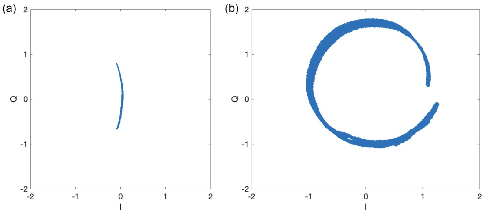
We also verified prominent differences in the spread of the arc on the I/Q plots from the 3.2 GHz and 24 GHz radars at the chest. Since 24 GHz radar is 7.5x higher in frequency than 3.2 GHz radar, it provides higher sensitivity in the phase term. Figure 5 shows that the 24 GHz radar traces out a near-circle on the I/Q plot with 7.5x more phase range than the arc traced by the 3.2 GHz radar.
Conclusion
We demonstrated the feasibility of measuring and monitoring cardiac signals using a mm-wave CW doppler radar with sensitivity sufficient even for carotid pulse detection. In the future, a non-contact mm-wave CW doppler radar when deployed in MRI, could provide a high sensitivity gating alternative. In addition to cardiac MRI, this could be useful even for brain pulsatile motion tracking in neuro-imaging.Acknowledgements
We gratefully acknowledge GE Healthcare for research support, amd funding support from NIH grants R01s EB009690 and EB012031 and U01s EB029427 and EB026412, and the NSF GRFP fellowship.References
[1] Oster J, Clifford GD. “Acquisition of electrocardiogram signals during magnetic resonance imaging. Physiol Meas. 2017 Jun;
[2] Scott AD, Keegan J, Firmin DN. Motion in cardiovascular MR imaging. Radiology. 2009 Feb;
[3] Gregory TS, Schmidt EJ, Zhang SH, Kwong RY, Stevenson WG, Murrow JR, Tse ZT. Left-ventricular mechanical activation and aortic-arch orientation recovered from magneto-hydrodynamic voltages observed in 12-lead ECGs obtained inside MRIs: a feasibility study. Ann Biomed Eng. 2014 Dec;42(12):2480-9;
[4] Solomon E, Rigie DS, Vahle T, Paška J, Bollenbeck J, Sodickson DK, Boada FE, Block KT, Chandarana H. Free-breathing radial imaging using a pilot-tone radiofrequency transmitter for detection of respiratory motion. Magn Reson Med. 2021 May;85(5):2672-2685;
[5] Vahle T, Bacher M, Rigie D, Fenchel M, Speier P, Bollenbeck J, Schäfers KP, Kiefer B, Boada FE. Respiratory Motion Detection and Correction for MR Using the Pilot Tone: Applications for MR and Simultaneous PET/MR Examinations. Invest Radiol. 2020 Mar;55(3):153-159;
[6] Wang, Dingyang, Sungwon Yoo, and Sung Ho Cho. 2020. "Experimental Comparison of IR-UWB Radar and FMCW Radar for Vital Signs," Sensors 20, no. 22: 6695;
[7] Anand, Suma, Lustig, Michael, “Beat Pilot Tone: Exploiting Preamplifier Intermodulation of UHF/SHF RF for Improved Motion Sensitivity over Pilot Tone Navigators,” ISMRM 2021;
[8] Suzuki, S. , Sun, G. , Hoshiga, M. , Kotani, K. and Asao, T. (2022) Noncontact Monitoring of Relative Changes in Blood Pressure Using Microwave Radar Sensors. Journal of Biomedical Science and Engineering, 15, 51-65;
[9] Kamshilin, Alexei A et al., “Accurate measurement of the pulse wave delay with imaging photoplethysmography.” Biomedical optics express vol. 7,12 5138-5147. 16 Nov. 2016.
Figures