4454
Evaluation of a vendor-agnostic scan-specific quality control acquisition for clinical whole-body MRI (WB-MRI) protocols1MRI Unit, Royal Marsden NHS Foundation Trust, Sutton, United Kingdom, 2Division of Radiotherapy and Imaging, The Institute of Cancer Research, London, United Kingdom, 3Centre for Medical Imaging, University College London, London, United Kingdom, 4Department of Imaging, Addenbrookes Hospital, Cambridge University Hospital NHS Foundation Trust, Cambridge, United Kingdom, 5Department of Radiology, University of Cambridge, Cambridge, United Kingdom
Synopsis
Keywords: Whole Body, Cancer, Quality Assurance / Quality Control
A short quality control (QC) acquisition and analysis process was developed previously to detect faulty RF coil elements and coil positioning errors in whole-body (WB) MRI. This work demonstrates the feasibility of this process on systems from three manufacturers and reports on the evaluation of this approach following its addition to the clinical WB-MRI protocol for all examinations over a period of six months on six scanners, providing on-going monitoring of image quality across 450 examinations. Two previously unidentified broken RF coil elements were detected, which were affecting clinical image quality, demonstrating the value of this active detection approach.Introduction
Phantom-based quality control (QC) is used routinely in clinical MRI departments and examination of images from individual radiofrequency (RF) receiver coil elements is encouraged to investigate issues1. It would be advantageous to also monitor image quality using data acquired during clinical examinations2. This could help to detect hardware issues earlier than routine QC and identify low image quality in multi-centre imaging trials.A rapid QC acquisition for whole-body (WB) MRI was previously developed to detect faulty coil elements and identify incorrectly positioned receiver coils3. This work evaluated the impact of adding the QC acquisition to the clinical WB-MRI protocol and demonstrated the feasibility of the approach on systems from three manufacturers.
Methods
The scan-specific QC acquisition has been described previously3 and consists of a single-slice coronal gradient echo sequence with six contiguous stations. Images are acquired using the automatically selected coil elements (saving each individual element image) and repeated using only the integral body coil. The total additional acquisition time is 82s (usual WB-MRI exam duration: 45-60 minutes).The QC acquisition was added to the clinical protocol for all WB-MRI examinations for patients with myeloma4 and patients with metastatic breast or prostate cancer5 within one institution over a period of approximately six months, a total of 450. This comprises six scanners, including three models (MAGNETOM Aera, Sola and Vida, Siemens Healthcare, Erlangen, Germany) and two field strengths (1.5T and 3T).
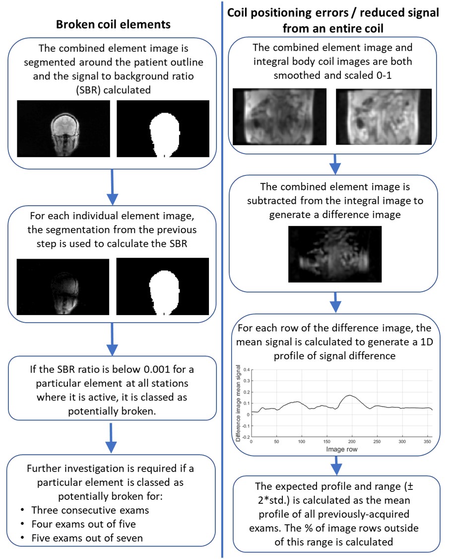
The offline processing pipeline3, summarised in figure 1, identifies images from individual RF coil elements with low signal compared to the combined element images, and regions of difference between the combined and integral body coil images. Criteria based on Shewhart charting6 were used to identify persistently faulty elements and the manufacturer’s coil QC routine used to confirm the fault. Difference profiles were plotted to identify coil mispositioning.
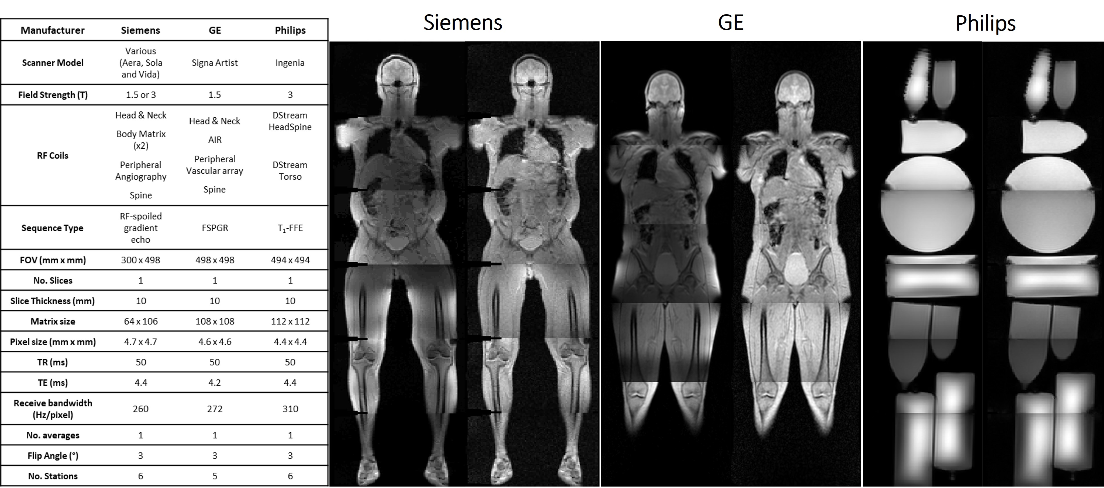
To assess the feasibility of the technique with scanners from two other manufacturers, equivalent acquisitions were developed, as summarised in figure 2. QC images were acquired from a volunteer or phantoms on each manufacturer’s system.
Volunteer and patient studies were approved by a Research Ethics Committee and an Institutional Review Board respectively. All volunteers gave written informed consent and the requirement for written patient consent was waived by the institution.
Results
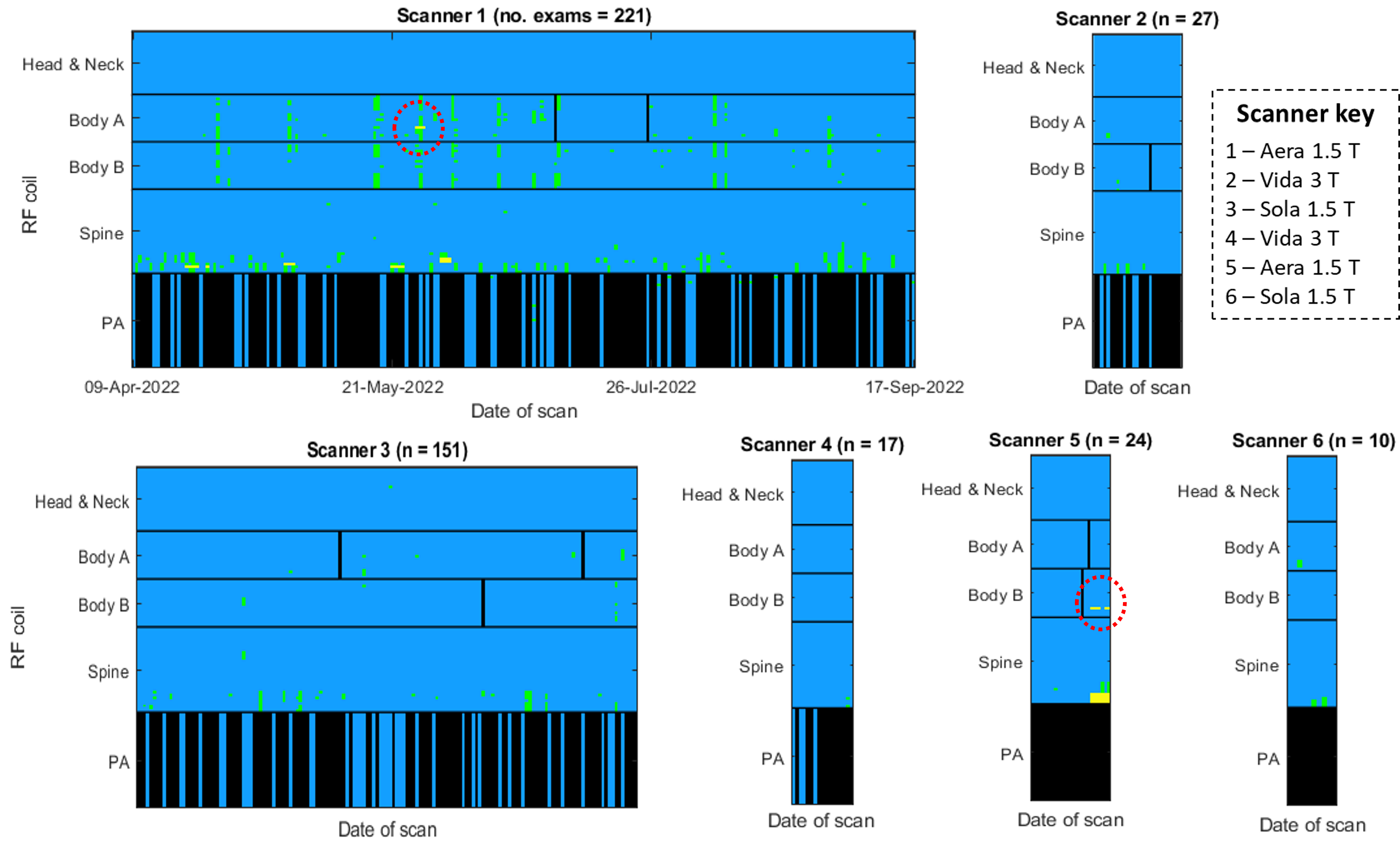
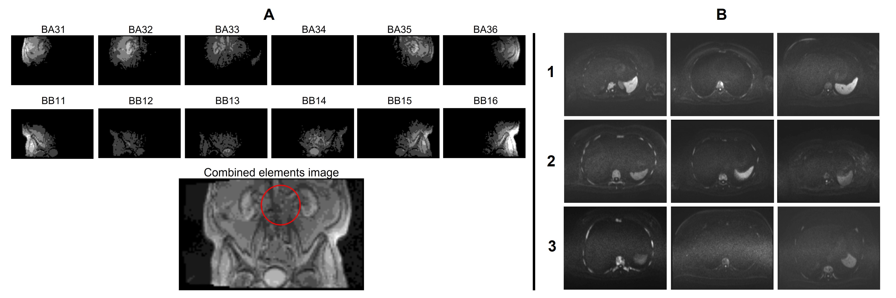
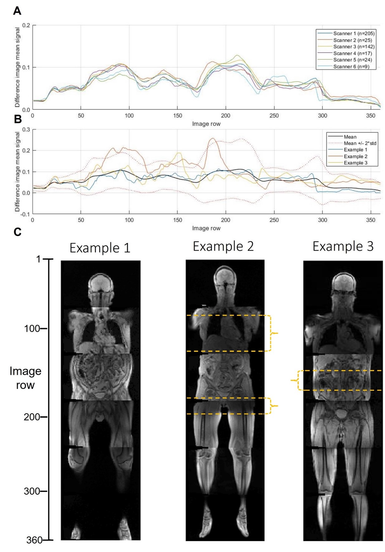
Figure 3 illustrates when low signal was recorded across all examinations. On two occasions, persistently faulty body matrix elements were identified, the manufacturer’s QC routine confirmed a fault and the coil was replaced. Reduced image quality was identified by a radiologist in a blinded comparison of the clinical diffusion-weighted images shown in figure 4. The manufacturer’s routine coil QC acquisitions did not detect any additional coil failures requiring coil replacement that were missed by this approach, indicating good sensitivity.The mean difference profile for each scanner is plotted in figure 5, along with example profiles from individual exams and the corresponding QC images. The mean percentage of image rows falling outside of the limits of agreement was 4.1% ±5.7%, with 11.5% of examinations exceeding 10% of rows outside of the limits.
Images from each manufacturer’s system are shown in figure 2. For Philips scanners, any element which will not significantly contribute to SNR is identified by a prescan and then deactivated, meaning that our processing pipeline is not able to detect faulty elements.
Discussion and Conclusions
Although clinically useful, WB-MRI is prone to low SNR and artefacts7 and would benefit from real-time monitoring of image quality. Our proposed QC technique detected two faulty coil elements affecting clinical image quality.The false positive results for the inferior elements of the spine coil may be due to the absence of the peripheral-angiography coil for some patient groups, which means the legs are raised outside of the QC imaging slice. This suggests that the proposed method may be less effective for detecting faults in the inferior spine coil elements compared to the body matrix coils. Specificity would be improved by reducing the number of stations in the QC acquisition to five for these patients. No other false positives were recorded outside of these cases.
The total additional imaging time due to the QC acquisitions was approximately 10 hours across all examinations. The same time, shared equally across scanners, would only be sufficient to run the manufacturer’s QC routine once per coil, leaving extended periods during which clinical image quality could be affected.
The difference profile graphs indicate that coils are generally positioned consistently by technicians at our centre, although this may not be the case for less experienced centres. Hence, this could provide a useful tool for early identification of image quality issues in multi-centre studies.
To maximise the value of this technique in multi-centre studies or clinical practice, it must be vendor-agnostic. This work has shown this to be the case for image acquisition, although our pipeline is not currently able to detect faulty elements on a Philips MR system. The detection of coil mispositioning is possible on all three systems, although further work is required to assess sensitivity and specificity across vendors.
The clinical application of this approach has demonstrated that it can detect faulty hardware earlier than routine QC, potentially reducing the number of sub-optimal examinations.
Acknowledgements
This project represents independent research funded by Cancer Research UK National Cancer Imaging Translational Accelerator (NCITA), the National Institute for Health and Care Research (NIHR) Biomedical Research Centre and the Clinical Research Facility in Imaging at The Royal Marsden NHS Foundation Trust and The Institute of Cancer Research, London. The views expressed are those of the author(s) and not necessarily those of the NIHR or the Department of Health and Social Care.
The authors thank Maria-Alexandra Olaru, Gregor Thoermer, and Mirko Appel at Siemens Healthineers, and David Higgins at Philips Healthcare for helpful discussions.
References
1. Charles-Edwards, G., Graves, M., and Weir, N., Artefacts, in Quality Control and Artefacts in Magnetic Resonance Imaging IPEM report 112., McRobbie, D.W., Editor. 2016, Institute of Physics and Engineering in Medicine: York.
2. Peltonen, J.I., Mäkelä, T., and Salli, E., MRI quality assurance based on 3D FLAIR brain images. Magnetic Resonance Materials in Physics, Biology and Medicine, 2018. 31(6): p. 689-699.
3. Keaveney, S., Hopkinson, G., Scurr, E., Olaru, M.-A., et al., Development of a scan-specific quality control acquisition for clinical whole-body MRI (WB-MRI) protocols, in Proceedings of the Joint Annual Meeting of ISMRM-ESMRMB. 2022: London, UK.
4. Messiou, C., Hillengass, J., Delorme, S., Lecouvet, F.E., et al., Guidelines for acquisition, interpretation, and reporting of whole-body MRI in myeloma: myeloma response assessment and diagnosis system (MY-RADS). Radiology, 2019. 291(1): p. 5-13.
5. Padhani, A.R., Lecouvet, F.E., Tunariu, N., Koh, D.-M., et al., METastasis reporting and data system for prostate cancer: practical guidelines for acquisition, interpretation, and reporting of whole-body magnetic resonance imaging-based evaluations of multiorgan involvement in advanced prostate cancer. European urology, 2017. 71(1): p. 81-92.
6. Simmons, A., Moore, E., and Williams, S.C., Quality control for functional magnetic resonance imaging using automated data analysis and Shewhart charting. Magnetic Resonance in Medicine: An Official Journal of the International Society for Magnetic Resonance in Medicine, 1999. 41(6): p. 1274-1278.
7. Koh, D.-M., Blackledge, M., Padhani, A.R., Takahara, T., et al., Whole-body diffusion-weighted MRI: tips, tricks, and pitfalls. American Journal of Roentgenology, 2012. 199(2): p. 252-262.
Figures