4432
GIRF-based characterization of a novel cryogen-free HTS magnet1Neoscan Solutions GmbH, Magdeburg, Germany, 2Otto-von-Guericke University, Magdeburg, Germany, 3Research Campus STIMULATE, Otto-von-Guericke University, Magdeburg, Germany
Synopsis
Keywords: System Imperfections: Measurement & Correction, Gradients, eddy currents
We characterized our new 1.5 T HTS magnet via GIRF determination. Analysis of time scales showed that relevant first-order eddy currents exhibit time constant of less then 200 µs. This finding is a promising characterization of our system but requires further investigations.Introduction
Rapidly switching gradient coils induces eddy currents in all conductive parts of an MRI magnet. These eddy currents are responsible for image artifacts and gradient induced magnet heating. However, time scales and magnitudes are typically a complex function of shielding efficiency as well as geometry, temperature, and materials of the surrounding parts.To characterize gradient induced interactions in our novel 1.5 T neonatal MR scanner1 (cryogen-free, HTS-based , actively shielded), we determined linear (i.e. first-order) eddy currents via the gradient impulse response function (GIRF) of the gradient system and analyzed the involved time scales.
Methods
All measurements were performed on our 1.5 T neonatal MR system1. All three channels of the gradient system, including the gradient power amplifier, were characterized by determining the self-response via the GIRF.An MR pulse sequence for GIRF determination was designed based on the Thin-Slice method2 realizing a series of 12 triangular gradient pulses with peak amplitudes ranging from 5 mT/m to 16 mT/m with fixed slew rate of 100 T/m/s. Parameters and timing were chosen similar to Stich et al.3 (FA: 90°, TR: 1 s, slice thickness: 5 mm, dwell time $$$\Delta t$$$: 9.8 µs, slice offset $$$\Delta x$$$: 4 cm, number of averages: 60).
Data sets with opposite gradient polarity and opposite slice positions were used to correct for potential bias introduced by static or dynamic $$$B_0$$$ changes, or concomitant fields, before the effective gradient waveform $$$G_{\text{out}}(t)$$$ was determined according to $$$G_{\text{out}}(t) = \frac{\Delta\phi(t)}{\gamma\Delta x \Delta t}$$$. Finally, the GIRF $$$H(f)$$$ was estimated in a least-squares sense4:
$$ H(f)= \frac{\sum_{i=1}^{12}{G^i_{\text{in}}}^*G^i_{\text{out}}}{\sum_{i=1}^{12}{G^i_{\text{in}}}^*G^i_{\text{in}}}$$
where $$$G^i_{\text{in}}$$$ is the nominal shape of the $$$i$$$-th gradient pulse.
To investigate the effect of gradient induced heating, temperature sensors at the inner thermal shield and at the magnet coil where read while running a slew rate intense pulse sequence (3D DESS, resolution: 1.5 mm3 , FOV: 192 mm3, TE: 2 ms, TR: 6 ms, BW: 1000 Hz/px, TACQ 98 s).
Measurements were carried out using a doped-water cylindrical phantom.
Results
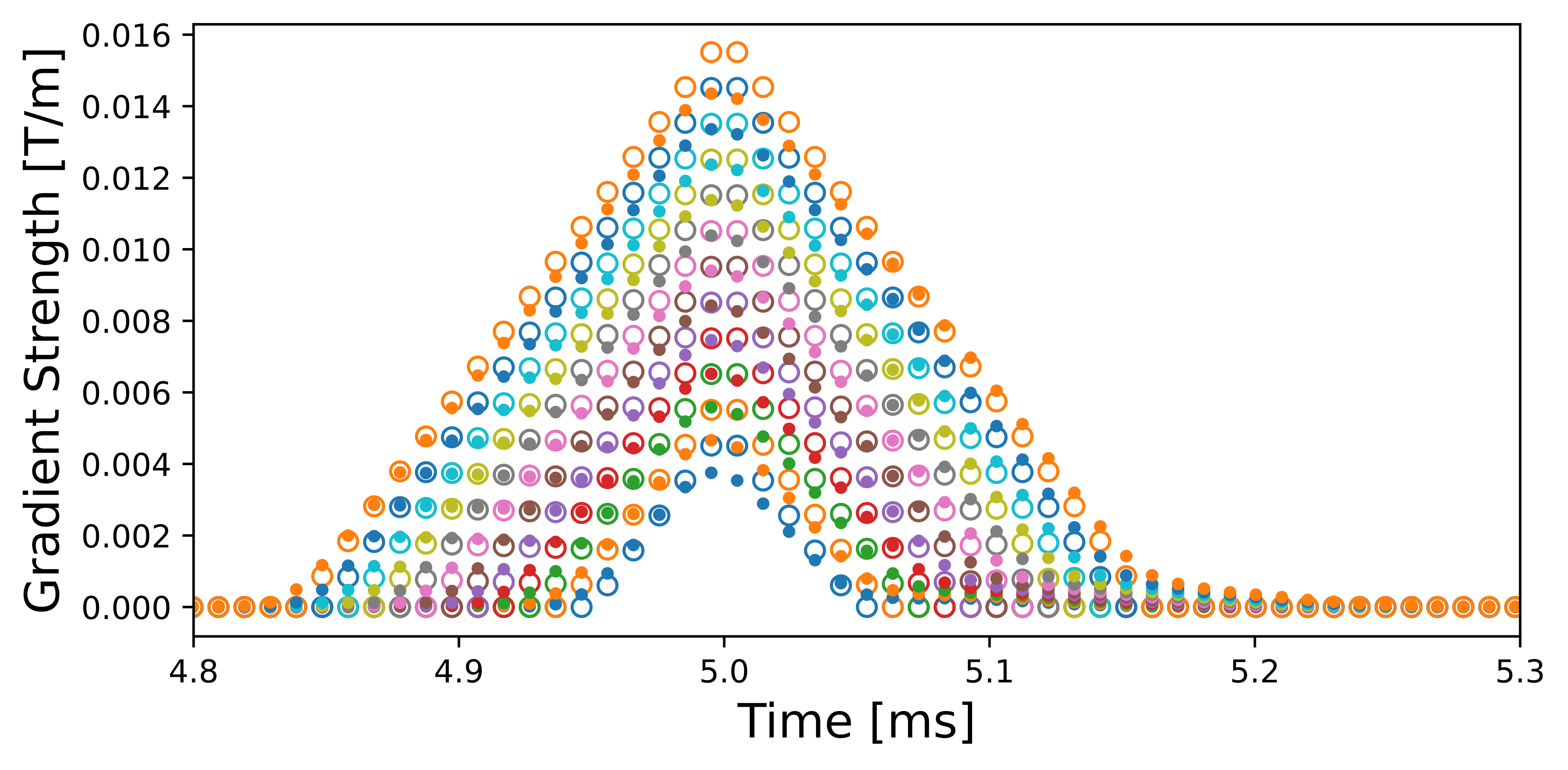
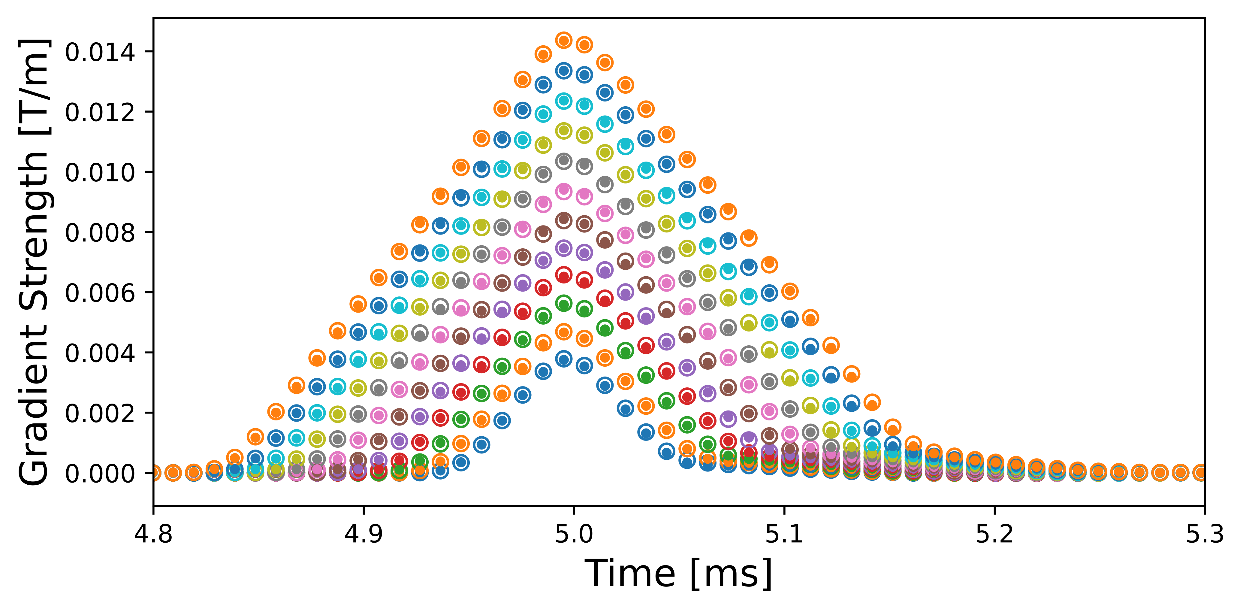
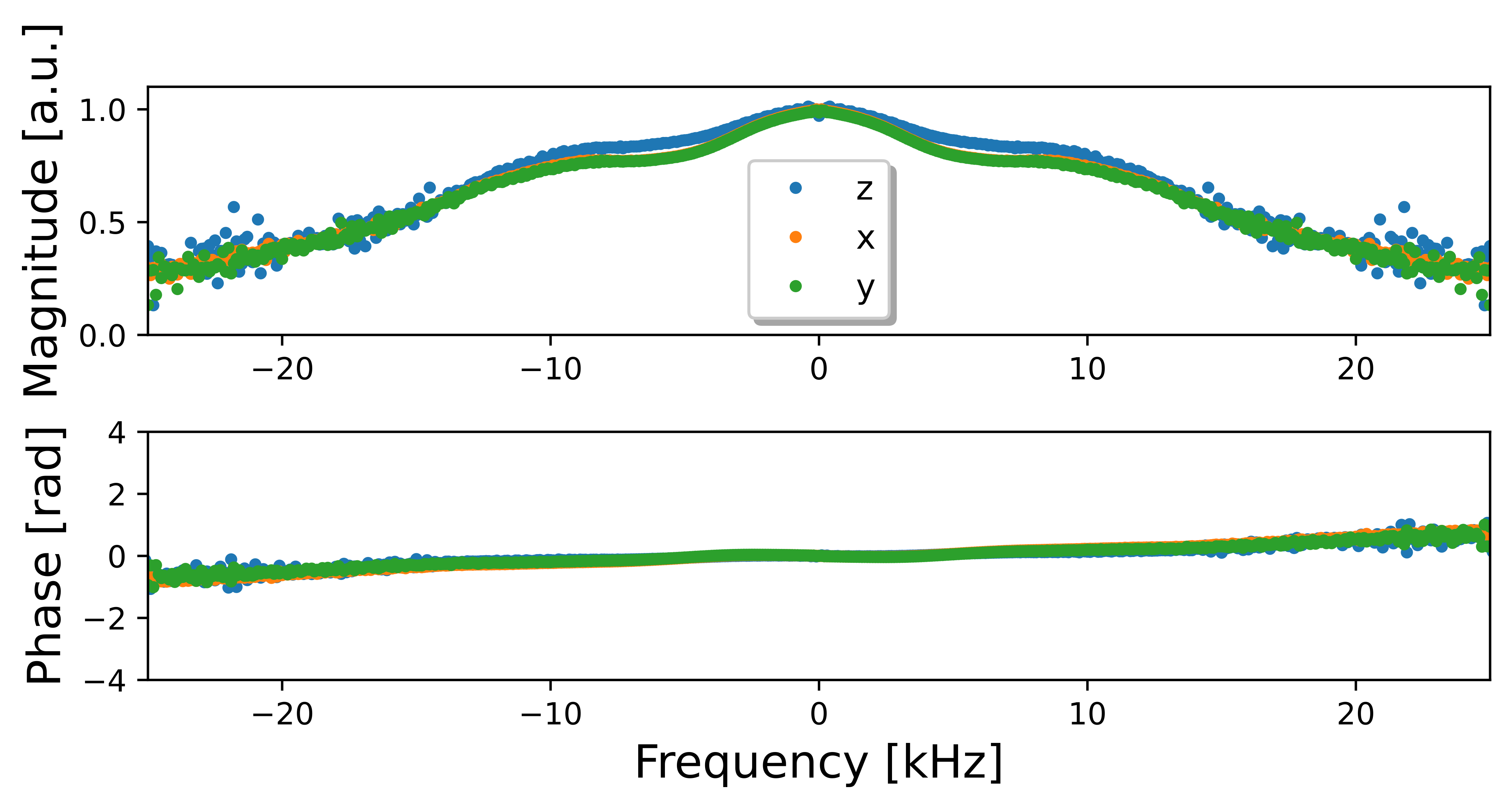
Figure 1 shows the experimentally determined gradient waveforms in comparison to the nominal waveforms for the $$$x$$$-channel of the gradient system. The determined GIRF for this channel allows to accurately predict the distortions (Figure 2).Figure 3 shows the determined GIRFs in frequency domain.The frequency response exhibits a FWHM bandwidth of about 30 kHz for all channels and the positive linear slope in the phase indicates that RF/ADC events are slightly delayed with respect to the gradients. The $$$z$$$-channel shows less damping in the frequency response compared to $$$x$$$ and $$$y$$$, most likely due different coil design.
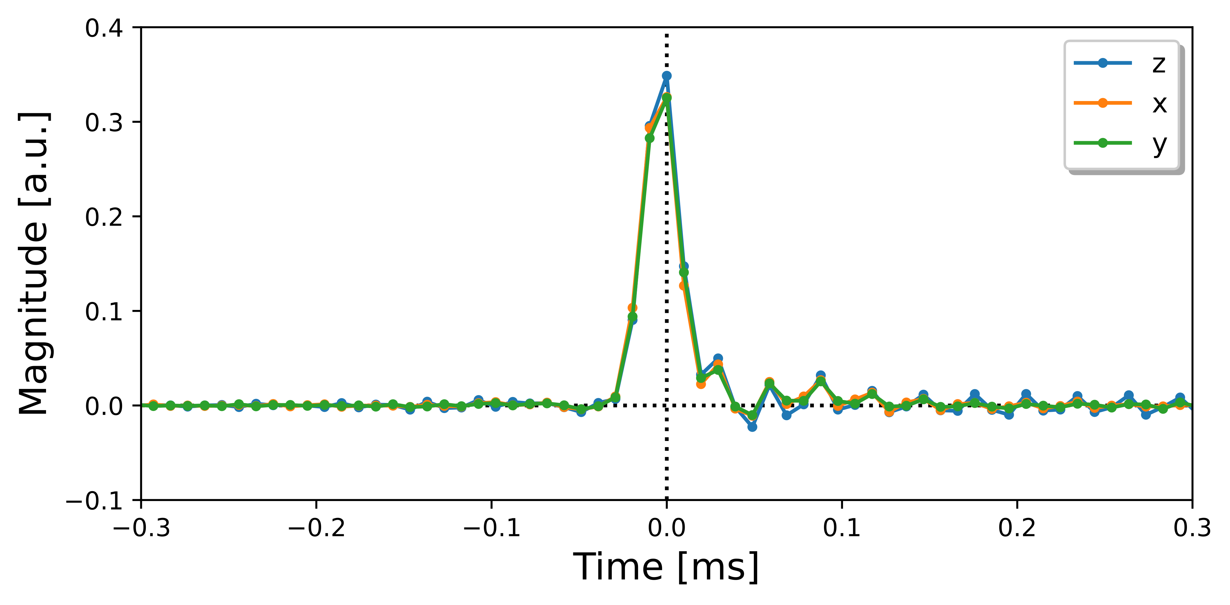
The time domain representation (Figure 4) reveals the main dynamics of the decaying first-order eddy currents happens within 100 µs and eddy currents decay almost completely within 200 µs.
The DESS pulse sequence was repeated 4 times during an interval of about 15 min and resulted in a temperature increase of 0.06 K (inner thermal shield) and 0.0025 K (magnet coil), respectively.
Discussion and Conclusion
In this work, we characterized the gradient system of a novel HTS magnet via GIRF determination. Analysis of the relevant time scales showed, in contrast to commonly used LTS systems5, only short-term eddy currents with time constants in the range of hundreds of micro seconds.Gradient induced heating resulted in a moderate temperature rise in the inner thermal shield and a minimal rise in the magnet coil.
Our hypotheses for the absence of mid- and long-term first-order eddy currents are twofold: First, our HTS magnet features a small ratio of the gradient coil size to the magnet bore diameter, which is a known factor for the intensity of generated eddy current fields6. Second, the cryogen-free magnet design features significantly less abundance of cold conductive material, a known source for long-term eddy currents7.
While this first characterization is promising for the overall magnet design, an evaluation of the hypotheses requires further investigations, including characterization and analysis of zero-th order ($$$B_0$$$) eddy currents.
Acknowledgements
No acknowledgement found.References
[1] Li et al. "A cryogen-free actively shielded HTS magnet for a 1.5 T MRI system." Proc. of the 27th ISMRM (2019).
[2] Duyn et al., et al. "Simple correction method for k-space trajectory deviations in MRI." Journal of Magnetic Resonance 132.1 (1998): 150-153.
[3] Stich et al. "Waveform pre‐emphasis based on the gradient system transfer function." Magnetic resonance in medicine 80.4 (2018): 1521-1532.
[4] Vanessjo et al. "Gradient system characterization by impulse response measurements with a dynamic field camera." Magnetic resonance in medicine 69.2 (2013): 583-593.
[5] Spees et al. "Quantification and compensation of eddy-current-induced magnetic-field gradients." Journal of magnetic resonance 212.1 (2011): 116-123.
[6] Ahn et al. "Analysis of eddy currents in nuclear magnetic resonance imaging." Magnetic Resonance in Medicine - Wiley Online Library
[7] Bedea et al. "Eddy current effects in MRI superconducting magnets." IEEE transactions on magnetics 33.2 (1997): 1330-1333.
Figures