4430
A 16-channel MC and RF hybrid system for B0 shimming and B1 reception: a preliminary prototype1Department of Biomedical Engineering, Columbia University in the City of New York, New York, NY, United States, 2Department of Radiology, Columbia University Medical Center, New York, NY, United States, 3Columbia Magnetic Resonance Research Center, Columbia University in the City of New York, New York, NY, United States
Synopsis
Keywords: Hybrid & Novel Systems Technology, RF Arrays & Systems, RF Rx array, AC/DC coil, Hybrid RF and shimming
We explore the potential of a hybrid approach in which RF receive elements are driven with direct current for B0 shimming (RF+MC) aided with multicoil shim-only elements (MC-only) to overcome the challenging B0 inhomogeneities in the frontal brain. A proof-of-concept implementation consisting of 16 RF+MC elements and 18 MC-only elements is presented. Simulations have shown minimal SNR loss despite the proximity of MC-only elements. Furthermore, the B0 shimming performance of this preliminary setup outperformed 3rd and 5th order SH shimming despite its rudimentary design. Future work will focus on optimizing the B0 performance while minimizing the MC-to-RF coupling.Introduction
Multicoil (MC) B0 shimming systems employ a multitude of individually driven loops to flexibly and effectively control B0. MC systems have shown to improve B0 homogeneity in rodent and human brain1-3 compared to spherical harmonic (SH) systems, especially in brain regions that suffer from strong B0 distortions due to drastic changes in magnetic susceptibility.While dedicated MC elements provide the most uniform B0, the need for close proximity MC hardware and radio-frequency (RF) coils could lead to interactions, impacting the signal-to-noise ratio (SNR)4. Using the same elements for RF transmission and/or reception and B0 shimming can be advantageous in terms of coupling and space management5, however, due to the lower current and number of turns and other design tradeoffs, achievable B0 homogeneity has been suboptimal.
The purpose of this work is two-fold: (1) We provide a quantitative analysis of MC-to-RF coil coupling and minimization strategies to inform future MC design and placement at minimal SNR penalty; (2) We explore the potential of a hybrid approach in which RF receive elements are also driven with direct current for B0 shimming (referred to as RF+MC) aided with shim-only elements to overcome the challenging B0 inhomogeneities in the frontal brain.
A proof-of-concept implementation consisting of 16 RF+MC elements and 18 MC-only elements is presented.
Methods
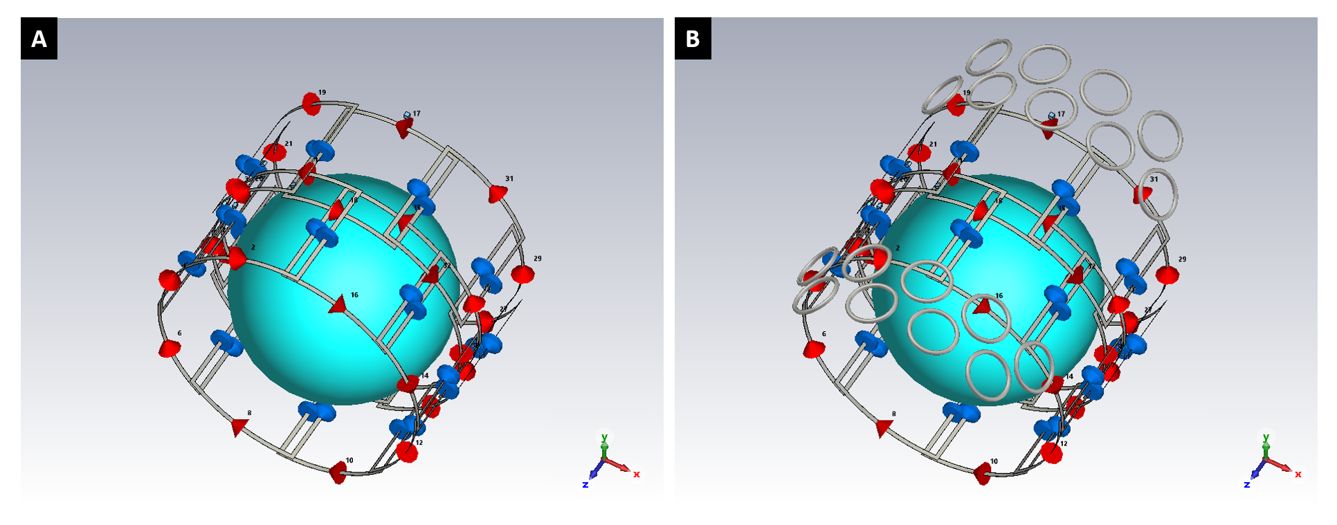
A 3T 16-channel head receive array was simulated in CST Studio Suite (Dassault Systèmes, France). The elements (138.5 × 135 mm2) were symmetrically distributed around a cylindrical surface (radius: 151.5 mm) in two rows of 8 loops each. Each element was tuned to 123 MHz, matched to 50 Ω and geometrically decoupled to its nearest neighbors.To quantify the effect of the presence of the MC-only elements on SNR, two configurations were simulated (Figure 1): (1) the 16-channel RF array; (2) the 16-channel RF array with 18 MC-only shim elements distributed frontally above and below the RF coil similar to Juchem et al.4. SNR was calculated as $$$SNR= \sqrt{{B_1^{-*}R^{-1} B^-_1}}$$$, where $$$R = \int_{}^{}\sigma E_i\cdot E_j^* dV$$$ is the noise covariance matrix6.
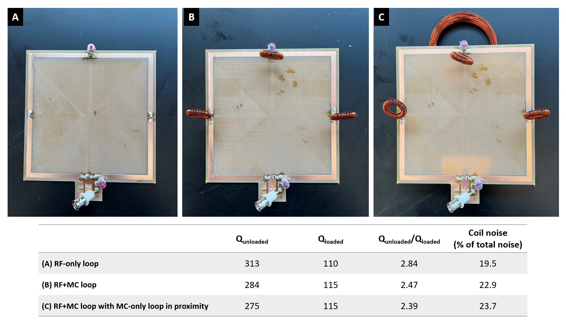
RF+MC capability can be achieved with RF chokes across the tuning capacitors5. The effect of the RF chokes, which were not included in the simulations, on the Q ratio of a single loop RF coil was measured in three configurations: (1) conventional RF-only, (2) RF+MC and (3) RF+MC with MC-only element in proximity. The RF chokes were hand-made by winding 59 turns of 22 AWG copper wire on a 3D printed toroidal support (OD/ID: 22/14 mm), which resulted in an inductance L ≈ 1.5 𝜇H.
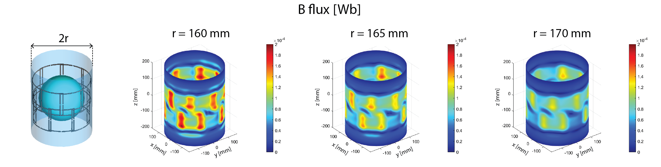
To guide the placement of the MC-only elements to minimize MC-to-RF coupling due to mutual inductance, the magnetic flux through three cylindrical surfaces with radii 160, 165, 170 mm was calculated. The flux on the cylindrical surfaces was sampled using a circular mask (radius: 25 mm, i.e. MC-only elements radius) and multiplied by 40 MC turns. For each surface, a flux map is obtained by assigning to each coordinate the magnitude of the flux through the circular mask centered in that location.
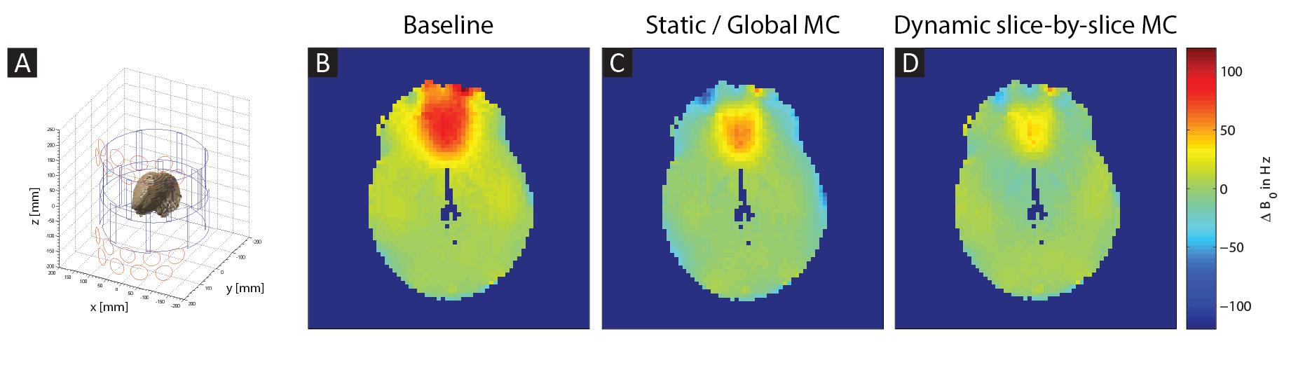
The B0 shimming capacity of the setup was investigated by calculating the best possible MC shims for 139 in vivo full brain B0 maps retrospectively collected7 in accordance with the Institutional Review Board of Columbia University. Biot-Savart static and dynamic B0 shim simulations were performed assuming maximum currents in each element of ±1 A. RF+MC elements were modeled with one turn of wire, while MC-only elements were modeled with 40 turns8-9.
Results
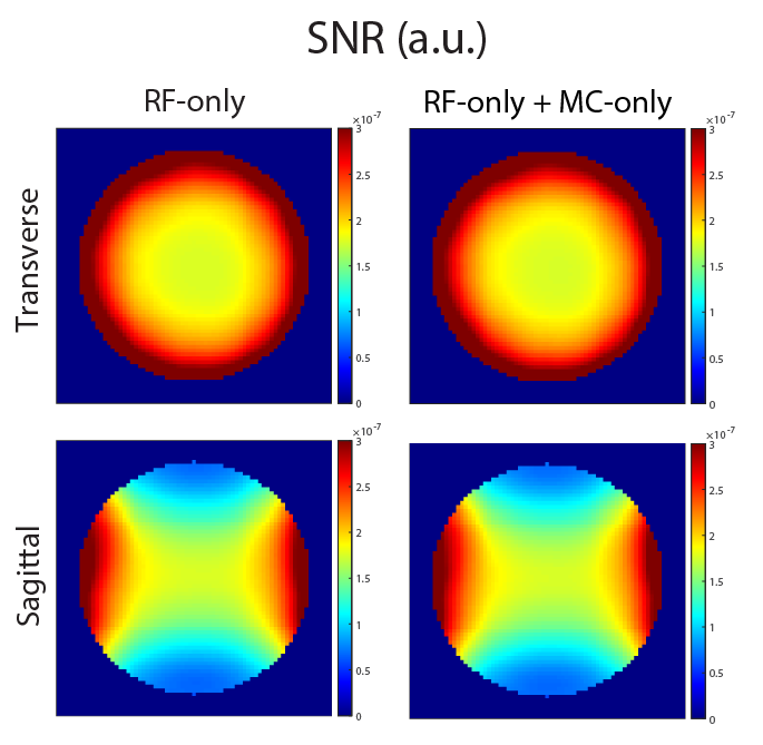
The presence of the MC-only elements did not affect the simulated SNR of the 16-channel array (Figure 2).In a single loop, the introduction of the RF chokes decreased the Qunloaded/Qloaded by 13% (i.e. coil losses increased from 19.5% to 22.9%). Qunloaded/Qloaded further decreased by 3% when the MC-only element was nearby (i.e. coil noise increased to 23.7%) (Figure 3).
Figure 4 shows the magnetic field flux through three cylindrical surfaces surrounding the RF+MC coil. As expected, as the distance between the MC-only elements and RF+MC coil increases (i.e. as r increases) the flux decreases. For |z|>125 mm, corresponding to the location of the MC-only elements in our prototype, a lower flux region is observed (dark blue bands).
Figure 5 shows an exemplary shimming result. Over all cases, the average standard deviation across the volume of the brain was reduced from 22.4 ± 4.3 Hz to 16.6 ± 3.1 Hz for a full brain static shim, and to 12.5 ± 2.3 Hz in dynamic slice-by-slice shimming, outperforming 3rd and 5th order SH shimming, respectively.
Conclusions
In this preliminary work we have investigated the feasibility of a hybrid MC-only plus RF+MC system.Simulations have shown minimal SNR loss despite the proximity of MC-only elements. However, the presence of RF chokes to enable the RF+MC capability is expected to introduce some SNR loss.
The B0 shimming performance of the employed preliminary setup outperformed 3rd and 5th order SH shimming despite its rudimentary design, i.e. positioning and size of the MC-only elements were not optimized for B0 shim performance. Future work will include such optimization within the engineering constraints of such an integrated hybrid system, informed by the coupling analysis here explored.
Acknowledgements
This work was supported by grant R01 EB030560 from the National Institutes of Health and was done under the rubric of the Columbia Magnetic Resonance Research Center at Columbia University in the City of New York.References
1. Juchem, C.; Brown, P. B.; Nixon, T. W.; McIntyre, S.; Rothman, D. L.; de Graaf, R. A., Multicoil shimming of the mouse brain. Magn Reson Med 2011, 66 (3), 893-900.
2. Juchem, C.; Nixon, T. W.; McIntyre, S.; Rothman, D. L.; de Graaf, R. A., Magnetic field modeling with a set of individual localized coils. J Magn Reson 2010, 204 (2), 281-9.
3. Juchem, C.; Umesh Rudrapatna, S.; Nixon, T. W.; de Graaf, R. A., Dynamic multi-coil technique (DYNAMITE) shimming for echo-planar imaging of the human brain at 7 Tesla. Neuroimage 2015, 105, 462-72.
4. Juchem, C.; Nixon, T. W.; McIntyre, S.; Boer, V. O.; Rothman, D. L.; de Graaf, R. A., Dynamic multi-coil shimming of the human brain at 7 T. J Magn Reson 2011, 212 (2), 280-8.
5. Stockmann, J. P.; Witzel, T.; Keil, B.; Polimeni, J. R.; Mareyam, A.; LaPierre, C.; Setsompop, K.; Wald, L. L., A 32-channel combined RF and B0 shim array for 3T brain imaging. Magn Reson Med 2016, 75 (1), 441-51.
6. Roemer, P. B.; Edelstein, W. A.; Hayes, C. E.; Souza, S. P.; Mueller, O. M., The NMR phased array. Magn. Reson. Med. 1990, 16 (2), 192-225.
7. Manly, J.; Rentería, M.; Avila-Rieger, J.; Turney, I.; Lao, P.; Seblova, D.; Fleurimont, J.; Martinez, M.; Brickman, A., Offspring Study of Racial and Ethnic Disparities in Alzheimer’s Disease: Objectives and Design. 2020.
8. Theilenberg S.; Ianniello, C.; Juchem, C., Design of a Hybrid Multi-Coil Array for B0 Shimming of the In Vivo Human Brain, Proc ISMRM, 2023, Toronto, Canada, under review.
9. Juchem, C.; Herman, P.; Sanganahalli, B. G.; Brown, P. B.; McIntyre, S.; Nixon, T. W.; Green, D.; Hyder, F.; de Graaf, R. A., DYNAmic Multi-coIl TEchnique (DYNAMITE) shimming of the rat brain at 11.7 T. NMR Biomed 2014, 27 (8), 897-906.
10. Gabriel, S.; Lau, R. W.; Gabriel, C., The dielectric properties of biological tissues: II. Measurements in the frequency range 10 Hz to 20 GHz. Phys Med Biol 1996, 41 (11), 2251-69.
Figures