4423
Feasibility of an optimized B0 passive shim helmet based on iron-oxide nanoparticle inks for human brain imaging
Hanne Vanduffel1, Nick Arango2, Willy Gsell1, Uwe Himmelreich3, Wim Vanduffel1, Cesar Parra1, Berkin Bilgic4, Clarissa Cooley4, Dimitios Sakellariou1, Rodrigo de Oliviera SIlva1, Lawrence Wald4, Rob Ameloot1, and Jason Stockmann4
1KULeuven, Leuven, Belgium, 2MIT, Cambridge, MA, United States, 3KULeuven, 3000, Belgium, 4Martinos Center, Charlestown, MA, United States
1KULeuven, Leuven, Belgium, 2MIT, Cambridge, MA, United States, 3KULeuven, 3000, Belgium, 4Martinos Center, Charlestown, MA, United States
Synopsis
Keywords: Shims, High-Field MRI
We present a new method for passive shimming based on 3D printed ferromagnetic inks that are fully compatible with the scanner RF coils. We show simulated B0 shim performance for designs that are optimized to shim the human brain for both a subject-specific passive shim insert and a robust general insert.Introduction
Subject-specific local B0 inhomogeneities degrade the geometric fidelity of MR images and introduce signal voids, banding, and other artifacts.[1]-[6] Active shims, which use sets of coils driven by typically, can only compensate B0 field up to 2nd order.[7] Dedicated multi-coil shim arrays have been shown to effectively shim up to 6th-order inhomogeneities.[8]-[12] However, these approaches can potentially interfere with the performance of RF Tx and Rx coils and take up scarce bore space. Alternatively, passive B0 shimming exploits the strategic placement of ferro-, dia- and paramagnetic materials for field shaping purposes.[13-[19] But the fabrication of subject-specific passive shim configurations is a manually intensive, error-prone and time-consuming process with limited efficacy for field correction, leading to limited adoption in the MR community. Ideally, a method can be developed that allows for the fully-automated fabrication of passive shim inserts that do not interfere with RF performance but have enough magnetic susceptibility to compensate for nuisance B0 fields in the brain. Our research explores the use of binder-jetting 3D printing to overcome the limitations of traditional passive shim configurations for brain imaging.[20] We embed small amounts of iron oxide nanoparticles in 3D-printed housing materials. The iron oxide is coated in a surfactant that limits the conductivity of the finished material, thus reducing interactions with RF fields.Methods
3D printing A binder-jetting 3D printer (10"x15"x8" build volume, 600x540dpi, 0.004" layer resolution, 0.020" minimum feature size; DOD-thermal HP11-printheads; Projet 660 3DSystems) was modified to allow the printing of custom inks and build material (Figure 1). A polymer-powder-polymethyl-methacrylate (dp= 50 μm BS150N) was used as build material in combination with a magnetic ink (MICR, VersaInk-Nano Black, dp = 50 nm, containing 30 wt% of magnetite nanoparticles). The binder ink consists of a 2:1 volume ratio of acetophenone and butanone and 25 mg mL−1 of N-octadecylsuccinic anhydride (TCI Europe). The passive shim geometry was designed as a close-fitting helmet-liner that fits inside a 1Tx/32Rx 7T Nova Medical coil (Figure 2). A quadratic programming algorithm minimizes the RMSE of the predicted B0 field and input in vivo B0 maps using the sensitivity matrix (including 0th-2nd-order scanner shims and 2144 3x3x3mm passive shim voxels), under the constraints that 0-100% of ferromagnetic ink can be printed per CAD voxel. The calculated correction values are converted to a printable VRML CAD format that contains the RGB grayscale value required in each CAD voxel to achieve the targeted B0 distribution in the brain (Figure 3). To make the passive shim design robust across different subjects, the optimized grayscale RGB distribution within the CAD geometry is determined by the RGB average of shim geometries derived from 5 in vivo shimmed B0 maps (obtained from the open-source Human Connectome database).[21][22]To test RF performance, a felt liner was homogeneously impregnated with 5 ml of the ferromagnetic ink (corresponding to three times more ink than the calculated CAD PS helmet ink volume). The liner was placed inside Nova Medical RF array to image an anthropomorphic head phantom. SNR maps and flip angle maps were acquired on the phantom before with and without the liner.[23][24][25] The unloaded quality factor (Qu) of a tuned RF receive loop for the two cases was measured on the lab bench with a double probe. Finally, a spin echo sequence was run at 100% SAR for 10 minutes, and an infrared camera was used to measure the temperature before and after.
Results
Figure 4 shows minimal impact of the felt liner on RF Rx and Tx performance. Bench measurements of Qu of Rx loop show insignificant changes on the order of 1-3%. No temperature change was detected during the heating test.B0 simulations comparing the baseline 0th-2nd shims to the subject-specific 3D printed passive shim insert for 5 subjects show a 45% average improvement in the standard deviation of B0. Figure 5 shows the simulated B0 maps for the baseline, subject-specific passive and general passive shim cases for subject #1.
Discussion
RF evaluation suggests that the low conducitivity of the ferromagnetic ink make it minimally disruptive to the scanner’s RF performance. The preliminary B0 shimming simulations show significant gains for 3D printed subject-specific passive shim inserts. In future work we will explore the possibility of using the 3D printed passive shim insert as the inner helmet surface of the RF coil itself, to economize on space close to the head. To make this approach to shimming clinically relevant, we will refine our optimization methods to imrpove robustness of the shim design across a broad range of subject brains. Optimization and CAD design software are available at https://rflab.martinos.org/.Acknowledgements
The authors acknowledge the support of NIH (R01EB028797), the KULeuven (Project. No. IDN/20/016, C14/21/111 and C3/21/027), the Research Foundation—Flanders (FWO SB Grant No. 1SB8519N), the European Commission for H2020 INSPiRE-Med (Grant No. 813120) and Innovation Human Brain Project SGA3 (Grant No. 945539). Data were provided in part by the Human Connectome Project, WU-Minn Consortium (Principal Investigators: David Van Essen and Kamil Ugurbil; 1U54MH091657).References
[1] K. Wachowicz, Res. Reports Nucl. Med. 2014, 1. [2] J. P. Stockmann, L. L. Wald, Neuroimage 2018, 168, 71. [3] C. Juchem, R. A. de Graaf, Anal. Biochem. 2017, 529, 17. [4] P. Jezzard, F. Centre, J. R. Hospital, O. Ox, n.d., 0. [5] K. M. Koch, X. Papademetris, D. L. Rothman, R. A. De Graaf, Phys. Med. Biol. 2006, 51, 6381. [6] D. F. Hillenbrand, K. M. Lo, W. F. B. Punchard, T. G. Reese, Rev. Lit. Arts Am. 2005, 4. [7] C. J. Wiggins, C. Choi, Y. Li, A. P. Lin, S. B. Thakur, E. M. Ratai, Magn. Reson. Mater. Physics, Biol. Med. 2021, 34, 179. [8] B. Pinho Meneses, J. P. Stockmann, N. Arango, P. F. Gapais, E. Giacomini, F. Mauconduit, V. Gras, N. Boulant, A. Vignaud, M. Luong, A. Amadon, Neuroimage 2022, 261, 119498. [9] B. P. Meneses, A. Amadon, Phys. Med. Biol. 2021, 66, DOI 10.1088/1361-6560/abc810. [10] F. Jia, H. Elshatlawy, A. Aghaeifar, Y. H. Chu, Y. C. Hsu, S. Littin, S. Kroboth, H. Yu, P. Amrein, X. Gao, W. Yang, P. LeVan, K. Scheffler, M. Zaitsev, Magn. Reson. Med. 2020, 83, 1442. [11] N. Arango, J. Stockmann, E. Adalsteinsson, J. White, Int. Soc. Magn. Reson. Med. 2019, 1462. [12] J. P. Stockmann, T. Witzel, B. Keil, J. R. Polimeni, A. Mareyam, C. Lapierre, K. Setsompop, L. L. Wald, Magn. Reson. Med. 2016, 75, 441. [13] F. Liu, J. Zhu, L. Xia, S. Crozier, 2011, 21, 60. [14] K. M. Koch, P. B. Brown, D. L. Rothman, R. A. de Graaf, J. Magn. Reson. 2006, 182, 66. [15] K. M. Koch, P. M. Brown, D. L. Rothman, R. A. De Graaf, 2006, 972, 2006. [16] A. Bungert, C. D. Chambers, M. Phillips, C. J. Evans, Neuroimage 2012, 59, 2167. [17] M. Bekiesińska-Figatowska, Polish J. Radiol. 2015, 80, 93. [18] J. L. Wilson, P. Jezzard, 2003, 1094, 1089. [19] Jesmanowicz, 2001, 9, 2001. [20] T. D. Ngo, A. Kashani, G. Imbalzano, K. T. Q. Nguyen, D. Hui, Compos. Part B Eng. 2018, 143, 172. [21] D. C. Van Essen, K. Ugurbil, E. Auerbach, D. Barch, T. E. J. Behrens, R. Bucholz, A. Chang, L. Chen, M. Corbetta, S. W. Curtiss, S. Della Penna, D. Feinberg, M. F. Glasser, N. Harel, A. C. Heath, L. Larson-Prior, D. Marcus, G. Michalareas, S. Moeller, R. Oostenveld, S. E. Petersen, F. Prior, B. L. Schlaggar, S. M. Smith, A. Z. Snyder, J. Xu, E. Yacoub, Neuroimage 2012, 62, 2222. [22] D. S. Marcus, J. Harwell, T. Olsen, M. Hodge, M. F. Glasser, F. Prior, M. Jenkinson, T. Laumann, S. W. Curtiss, D. C. Van Essen, Front. Neuroinform. 2011, 5, 1. [23] P. Kellman, E. R. McVeigh, Magn. Reson. Med. 2005, 54, 1439. [24] S. Chung, D. Kim, E. Breton, L. Axel, Magn. Reson. Med. 2010, 64, 439. [25] B. Guérin, J. P. Stockmann, M. Baboli, A. Torrado-Carvajal, A. V. Stenger, L. L. Wald, Magn. Reson. Med. 2016, 76, 540.Figures
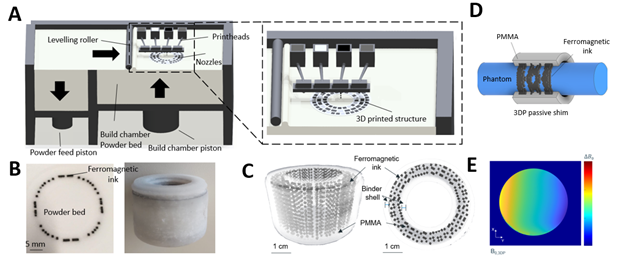
Figure 1: (A) Schematic overview
of the binder-jetting printer. The 3D-printed object is fabricated in a
bottom-up layer-by-layer approach by jetting inks on a PMMA powder layer. (B)
Left: picture of one PMMA powder layer with ferromagnetic ink jetted onto the
powder bed. (C) μ-CT scan of a printed
part used to analyze the printing performance of the CAD design resolution =
300 μm). (D) CAD design of a
ferromagnetic shim configuration rendering a 1st-order spherical
harmonic linear-gradient (E) on a cylindrical phantom at 9.4T.
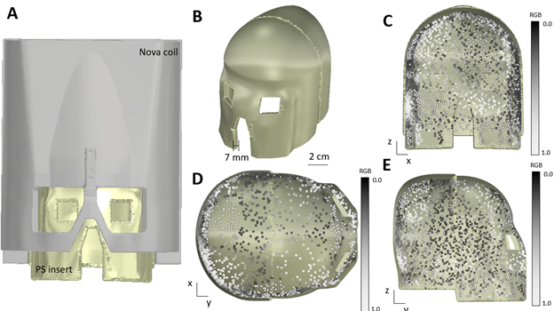
Figure 2: General CAD design
of passive shim helmet (A) Passive shim insert (yellow) is designed to fit
inside the 32ch Nova Medical coil. (C) Front view, (D) Top view, and (E) side
view of the passive shim helmet. Yellow: binder ink. Greyscale cubes:
ferromagnetic shimming voxels (2 mm x 2mm 2 x mm) with varying amounts of ink
printed. RGB of 0.0 = 100% ferromagnetic ink , RGB of 1.0 = 0% ferromagnetic
ink.
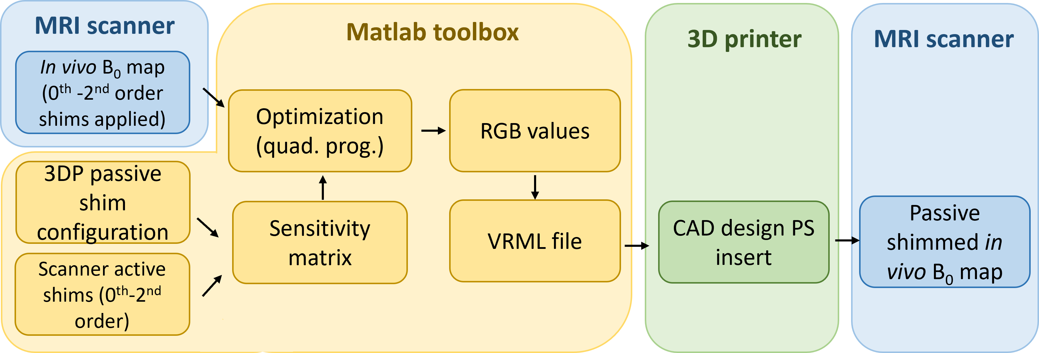
Figure 3:
Schematic overview of 3D printed passive design workflow. In vivo B0 maps and a
sensitivity matrix comprised of both the passive shim voxel basis set and the 0th
-2nd order active shim basis set is used as input for the quadrature
programming-based optimization toolbox in MATLAB. The ferromagnetic ink
required in each CAD voxel is converted to a printable VRML file.
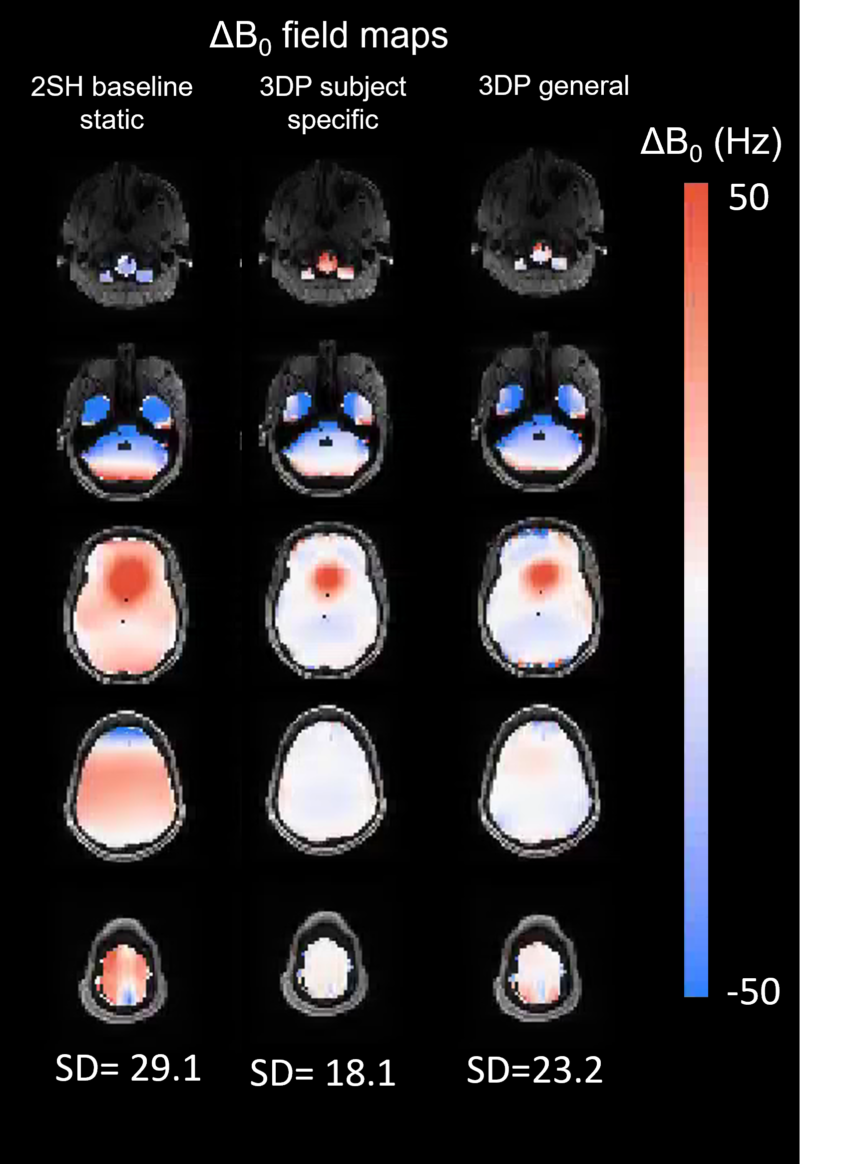
Figure 4: B0 simulations for subject #1 showing 5
representative slices. Column 1:Baseline ΔB0 fieldmap after 0th -
2nd order shims have been applied. Column 2: subject-specific 3D printed passive shim insert.
Column 3: General passive shim insert.
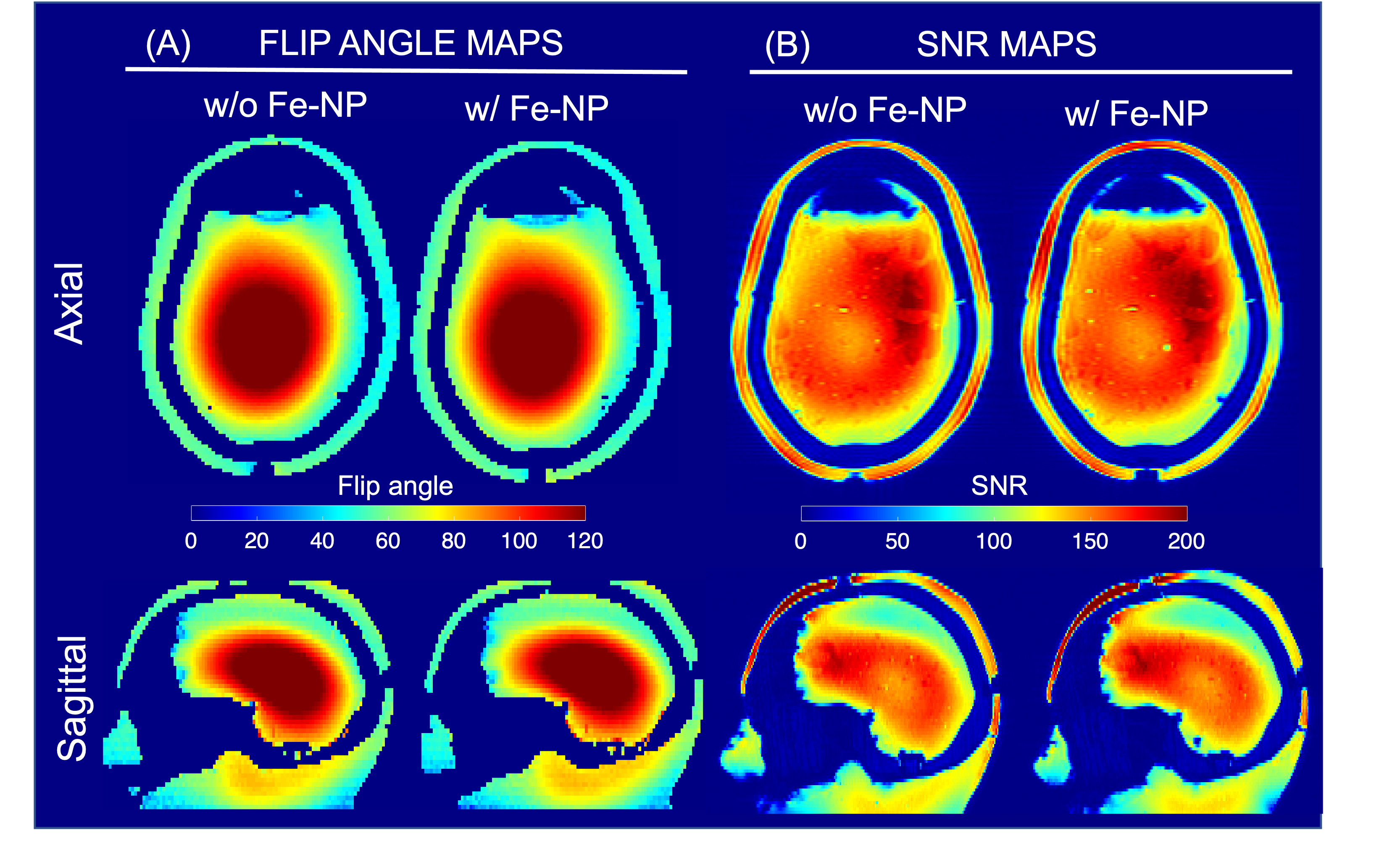
Figure 5: Effect of
ferromagnetic impregnated liner on RF performance measured at 7T using an
anthropomorphic head phantom. (A) Flip angle maps acquired without (left) and
with the ferromagnetic liner (right) show no significant difference. (B) SNR
maps also show very little difference in receive sensitivity except for a small
change in the signal level at the scalp due to T2* dephasing caused by close
proximity of the ferromagnetic liner.
DOI: https://doi.org/10.58530/2023/4423