4422
Self-Grounded Bow-Tie Antennas Placed Perpendicular to B0 in a Helmet RF Array Improve B1+ Uniformity for Brain MRI at 7.0T1Berlin Ultrahigh Field Facility, Max-Delbrück Center for Molecular Medicine in the Helmholtz Association, Berlin, Germany, 2Theoretische Elektrotechnik Institut Hochfrequenz- und Halbleiter-Systemtechnologien, Technische Universität Berlin, Berlin, Germany, 3Chair of Medical Engineering, Technische Universität Berlin, Berlin, Germany, 4a joint cooperation between the Charité Medical Faculty and the Max-Delbrück Center for Molecular Medicine, Berlin, Germany, 5MRI.TOOLS GmbH, Berlin, Germany
Synopsis
Keywords: RF Arrays & Systems, Modelling, Brain MRI, UHF MRI, PTx
UHF-MR uses RF arrays to shape the magnetic field generated inside the brain. For brain MRI at 7T, a helmet shaped transmit RF array could be beneficial versus conventional annular configurations. Recognizing this opportunity this work examines the feasibility of a multi-channel TX helmet RF applicator using broadband Self-Grounded Bow-Tie (bbSGBT) antenna building blocks. The focus is on enhancing B1+ uniformity and coverage for brain MRI at 7.0T. Our findings obtained for the human head voxel model Duke demonstrate improved mean B1+ coverage and increased B1+ uniformity for the helmet configuration.
Introduction
The sensitivity gains at UHF-MR (B0≥7.0 T) benefits high spatial resolution brain MRI using RF transmitter (Tx) arrays. However, the short-wave length at 297 MHz might constitute an impediment for uniform transmission within the brain. Increasing the number of Tx antenna in a head RF array increases the degrees of freedom for homogenous magnetic field shaping1. RF arrays tailored for brain MRI at 7.0 T typically use annular Tx arrays2-4. Helmet configurations constitute a viable alternative to improve whole brain SNR4. This approach only works if the Tx elements placed perpendicular to B0 induce an H-field perpendicular to B0. Recognizing this opportunity this work examines the feasibility and benefits of a helmet RF array comprising eight Tx elements arranged in an annular array around the head, in conjunction with two Tx elements placed on top of the head, perpendicular to B0 and rotated 90°. This is benchmarked against a reference annular array comprised of 10 equally spaced Tx.Methods
Electromagnetic field (EMF) simulations where performed in CST Microwave Studio (CST Studio Suite 2020, Dassault Systèmes) on the head of the human voxel model Duke5 at 297.2 MHz, using broadband self-grounded bow-tie antenna (bbSGBT) Tx building blocks (Figure1A, shown in in a UWV coordinate system with B0 along the z-axis) arranged in two RF array configurations: i) helmet array: Eight bbSGBT Tx elements arranged in an equally spaced annular array plus two bbSGBT Tx elements placed above the head (Figure1B top); ii) annular array: 10 bbSGBT Tx elements arranged symmetrically around the head. (Figure1B bottom). For both configurations bbSGBT antennas are placed around the head in an annular arrangement so that Z and W always are in the same direction. For the helmet configuration (Figure1B-top), two Tx elements were positioned on top of the head such that the VW plane of the bbSGBT elements was in the XY plane. Alternatively, the two extra bbSGBT elements were placed perpendicular to B0, but rotated 90° so that the V-axis is in alignment with the Z-axis. B1+ and SAR distribution in the region of interest (ROI) covering the brain were calculated in Matlab 2021a. SAR calculations were averaged over 10g of tissue or phantom material (SAR10g)6.For transmission field shaping, a genetic algorithm7 was used in conjunction with unconstrained minimization (fminunc)8 implemented in the global optimization toolbox of Matlab 2021a. B1+ shimming was applied with three objectives: i) maximizing mean B1+ in the center of the ROI: ii) maximizing mean B1+ inside the full ROI; iii) minimizing the relative standard deviation (SD) of B1+ divided by the mean value of the Coefficient of Variation of B1+ (CoV=SD/mean)9 which increases B1+ uniformity at the cost of reduction of the peak B1+.
Results
A bbSGBT antenna placed perpendicular to B0 with the long axis aligned with the anterior-posterior direction generated an H-field perpendicular to B0 (Figure2A). If the long axis of the bbSGBT antenna is rotated 90° and aligned with the left-right direction, the induced H-field is parallel to B0 (Figure2C).. The latter setup represents the “dark mode”. Figure3 depicts B1+ maps and SAR10g distributions obtained for the helmet array and the annular array. Upon maximization of the transmission field strength in the centre of the brain, the annular array provided a mean B1+=11.81 μT/√kW, which was slightly higher than that produced by the helmet array (B1+=10.99 μT/√kW). However, the helmet array generated greater brain coverage (84%) versus the annular array (78%). Maximum SAR10g was 0.912 W/kg for the helmet array and 0.80 W/kg for the annular array (Figure3A,B). Static transmission field shimming in order to maximize mean B1+ across the brain provided a mean B1+=11.1±5.0 μT/√kW for the helmet array and B1+=13.7±6.5 μT/√kW for the annular array. Notwithstanding this mean B1+ performance, the annular array demonstrated a close-to-zero minimum B1+=0.01 μT/√kW in the center of the brain (Figure3C,D). Additionally, the helmet array provided enhanced ROI coverage (83%) versus the annular array (62%). Transmission field shimming focusing on B1+ uniformity resulted in a CoV=0.24 across the brain for the helmet array, vs. CoV=0.37 for the annular array(Figure3E,F).Discussion and Conclusion
Ensuing transmission field uniformity across the brain presents a challenge at UHF-MR due to wave length shortening. This constraint can be offset by using RF arrays for transmission. However, the head presents a small surface area, and thus the number of Tx elements arranged in an annular array around the head is limited. To offset this constraint, the helmet RF array takes advantage of two additional bbSGBT Tx elements placed on top of the head and positioned perpendicular to B0 with the long axis being aligned along the anterior-posterior direction. Our findings demonstrate that the helmet RF array enhanced B1+ coverage and B1+ uniformity across the brain compared to a conventional annular array. To conclude, our results provide a springboard for the implementation and application of a helmet array driven by broadband bbSGBTs at 7.0 T, 10.5 T and 14.0 T.Acknowledgements
This project has received funding from the European Research Council (ERC) under the European Union's Horizon 2020 research and innovation program under grant agreement No 743077 (ThermalMR) and from the Innovative Training Network (ITN) H2020-MSCA-ITN-2020-955625 of the Marie Skłodowska-Curie Actions of the European Union.References
1. Winter, L., et al. Design and evaluation of a hybrid radiofrequency applicator for magnetic resonance imaging and RF induced hyperthermia: electromagnetic field simulations up to 14.0 Tesla and proof-of-concept at 7.0 Tesla. PLoS One 8, e61661 (2013).
2. Oberacker, E., et al. Radiofrequency applicator concepts for thermal magnetic resonance of brain tumors at 297 MHz (7.0 Tesla). Int J Hyperthermia 37, 549-563 (2020).
3. Adriany, G., et al. Evaluation of a 16-channel transmitter for head imaging at 10.5 T. in 2019 International Conference on Electromagnetics in Advanced Applications (ICEAA) 1171-1174 (IEEE, 2019).
4. Avdievich, N.I., et al. A 32-element loop/dipole hybrid array for human head imaging at 7 T. Magnetic Resonance in Medicine 88, 1912-1926 (2022).
5. Christ, A. The virtual family project-development of anatomical whole-body models of two adults and two children. Proc. 23rd Annual Review of Progress in Applied Computational Electromagnetics (ACES) 2007 (2007).
6. IEEE Recommended Practice for Determining the Peak Spatial-Average Specific Absorption Rate (SAR) in the Human Head from Wireless Communications Devices: Measurement Techniques. IEEE Std 1528-2013 (Revision of IEEE Std 1528-2003), 1-246 (2013).
7. Chipperfield, A., Fleming, P. & Fonseca, C. Genetic algorithm tools for control systems engineering. in Proceedings of adaptive computing in engineering design and control, Vol. 128 133 (Plymouth Engineering Design Centre UK, 1994).
8. Coleman T, Branch MA, Grace A. Optimization Toolbox Matlab 7.8.0. Published online 2009.
9. Mao, W., Smith, M.B. & Collins, C.M. Exploring the limits of RF shimming for high-field MRI of the human head. Magn Reson Med 56, 918-922 (2006).
Figures
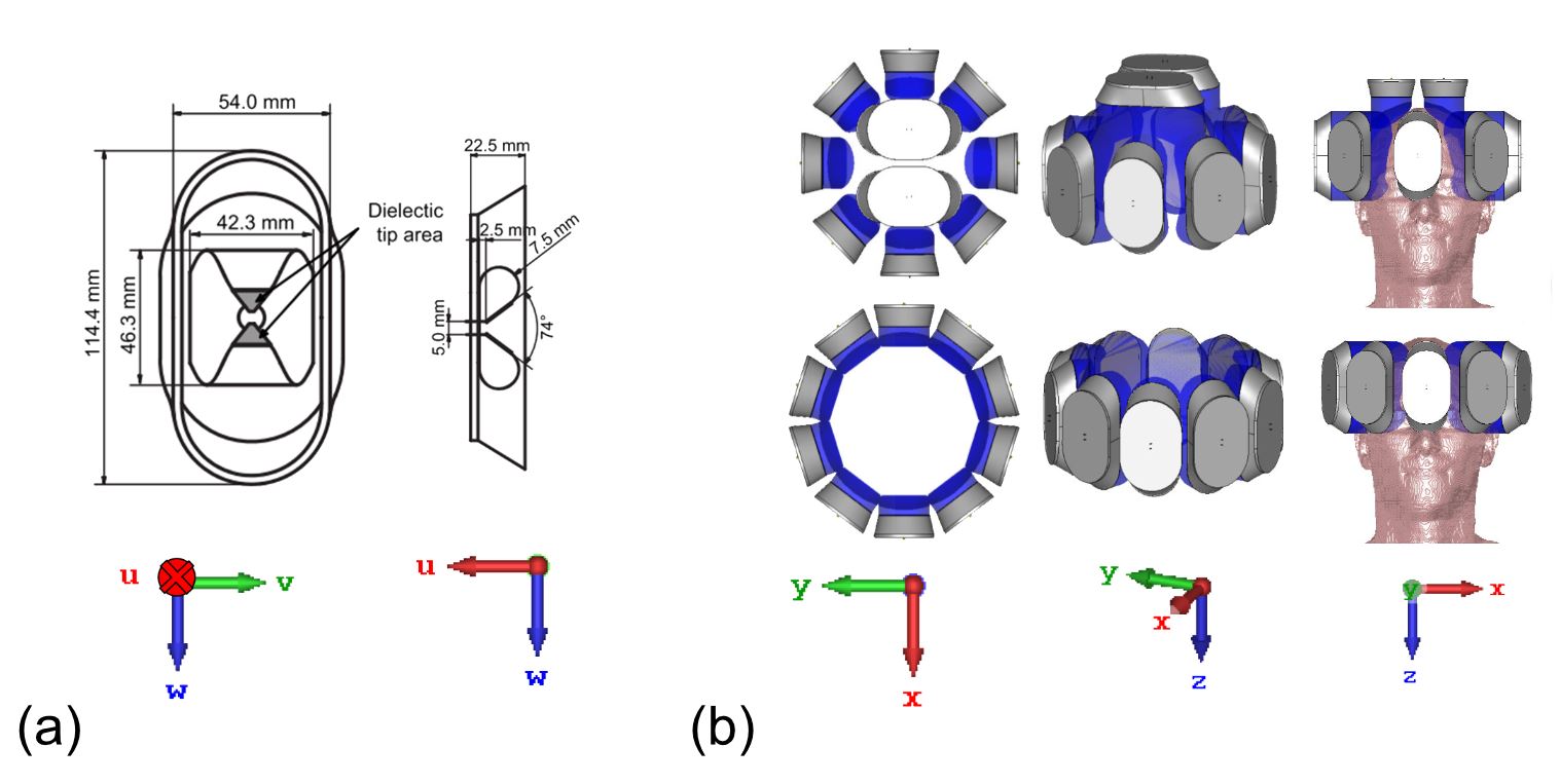
Figure 1: (A) Schematic of a bbSGBT building block in a UWV coordinate system frame. (B) RF-applicator configurations in XYZ coordinate system used in the EMF simulations: helmet array (top); annular array (bottom). Each array comprises 10 bbSGBT Tx elements for transmission.
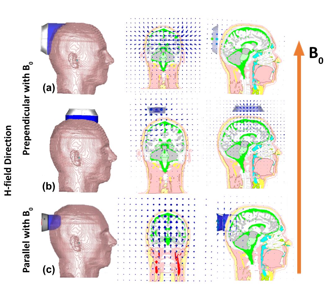
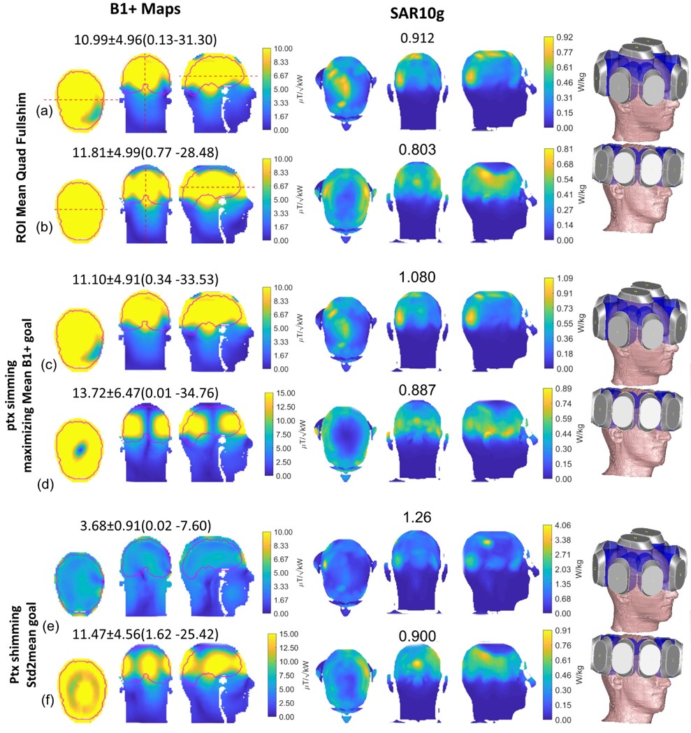
Figure 3: B1+ and SAR distribution maps obtained from static pTx shimming using the helmet array (a, c, e) and the annular array (b, d, f) on the human voxel model Duke. The annotations highlight [Mean±SD(min-Max)] for B1+( μT/√kW).