4418
Design of human brain shim coil with high-density wire pattern translated from Stream Function
Shengyue Su1 and Anke Henning1
1Advance Imaging Research Center, University of Texas Southwestern Medical Center, Dallas, TX, United States
1Advance Imaging Research Center, University of Texas Southwestern Medical Center, Dallas, TX, United States
Synopsis
Keywords: Shims, New Devices, Simulations
In this work, we propose a B0 shim coil design method based on high-density wire pattern discretized from stream function optimization. We demonstrate that the magnetic field generated by the designed shim coil can fully match the theoretical magnetic field generated by continuous stream functions. We compared the performance of different current-carry surfaces over shim ability for stream function optimization. We also evaluated the impact of current limitation for the discretized coil on B0 shim result and power dissipation.Introduction
B0 inhomogeneity caused by magnetic susceptibility differences among tissues and air grows with static magnetic field increases resulting in image distortions and signal losses, which is a significant drawback in Ultra-High Field MRI despite its high SNR.Although 2nd- or 3rd-order Spherical Harmonic (SH) shimming coils have been integrated into most 7T human MRI scanner, residual B0 inhomogeneity is relatively high for MR Imaging. Subject-based Stream Function optimization method1 has been introduced to design Multi-Coil B0 shimming arrays. However, existing practical implementations approximate the complex current pattern by single loops and result in advanced Matrix coils2-5, in which shim performance may deviate from numerically optimized continuous stream functions.
To preserve theoretically achievable shim performance, we propose a B0 shim coil design method to generate an optimal gradient-coil-like high-density wire pattern with more loops selected from stream functions for practical implementation. We simulated and evaluated the performance of cylinder (2D) and helmet (3D) current-carrying surfaces with a 3D gradient coil design method6,7 on human head B0 maps.
Methods
Surface: Two types of current-carrying surfaces are used for shim coil design (Figure 1). One is cylindrical with lengths ranging from 250mm to 500mm; another is a helmet-like surface composed of a cylinder and a partial sphere. Both have a radius of 170mm.Database: 12 B0 brain maps acquired on a 7T Philips system are randomly separated into the design-set (8 maps) and test-set (4 maps) in coil optimization. The 2nd order SH B0 shim is applied to these maps and set as the baseline $$$B_{z,0}(\vec{r})$$$. The inhomogeneity is quantified by standard deviation (SD) $$$\sigma(B_0)$$$, and the database has an average SD of 39.29Hz ± 4.51Hz.
Optimal stream function: Magnetic field can be simulated with Biot-Savart law from the stream function (SF) $$$\varphi$$$ of current density $$$\vec{J}(\varphi)$$$ on a given surface $$$S$$$, the simulation was based on the ThinWire toolbox8 which we modified to extend to 3D surfaces. Power dissipation is regularized to satisfy amplifier constraints and maintain safe temperature. Instead of calculating SF for each brain map and analyzing the principal component with SVD to get a single stream function4, we equally combined all maps in one design-set inside the cost function thus searching for only one optimal SF for all maps. Multiplier $$$m_i$$$ is pre-optimized by particle-swarm algorithm to balance inhomogeneity differences among maps. The SF is optimized by minimizing the residual magnetic field of the whole brain, with cost function$$\min_{\varphi}\sum_{i=1}^{8}\lVert m_{i}B_{z}(\varphi,\vec{r})+B_{z,0}^{i}(\vec{r})\rVert_{2}^{2}\text{,}\;\text{subject}\;\text{to}\;\frac{1}{\tau\sigma}\int_{S}\lVert \vec{J}(\varphi)\rVert_{2}^{2}dS<P_{assigned}.$$
Discretization and optimal current input: Resulting stream functions are discretized into wire patterns considering wire diameter and minimum distance to provide a practically implementable head shim coil. The wire patterns are grouped into individual shim channels, each of which will be jointly connected to one shim amplifier module when manufactured. The magnetic field strength of the kth channel with one ampere input $$$B_{k,z}(\vec{r})$$$ is calculated from the realistic wire paths. Thus, the residual field map for subject $$$i$$$ is,$$B_{z,after}(\vec{r})=B_{z,0}^{i}(\vec{r})+\sum_{k=1}^{N_c}I_{k}B_{k,z}(\vec{r})$$with channel k’s input current $$$I_{k}$$$, and we minimize the inhomogeneity with ConsTru Algorithm9 under a given current limitation:$$\min_{I_{k}}\lVert B_{z,0}^{i}(\vec{r})+\sum_{k=1}^{N_c}I_{k}B_{k,z} (\vec{r})\rVert _2^{2}\text{,}\;\text{subject}\;\text{to}\;\max{(I_k)}<\text{current}\;\text{limitation.}$$The self-resistance $$$R_k$$$ of the coil is calculated with the conductivity of the wire, and the wire power dissipation is $$$P=\sum_{k=1}^{N_c}I_{k}^{2}R_{k}$$$.
Result and Discussion
We optimized stream functions (Figure 2) on different current-carrying surfaces, and then discretized them into wire patterns with grouped channels (Figure 3). The coil channel numbers are 28 (250mm), 25 (300mm), 24 (350mm), 26 (400mm), 22 (500mm), and 21 (Helmet). The similarities between the theoretical field $$$B_z(\varphi,\vec{r})$$$ and the discrete coil-generated field $$$B_{z,coil}(\vec{r})=\sum_{k=1}^{N_c}I_{k}B_{k,z}(\vec{r})$$$ are 0.9910 (250mm), 0.9767 (300mm), 0.9878 (350mm), 0.9877 (400mm), 0.9920 (500mm), and 0.9837 (Helmet). Thus, our proposed discretization method can preserve the theoretical shim ability.We then optimized the shim channel-wise current input for each field map with various current limitations. The shim effect is evaluated by the inhomogeneity reduction compared to the baseline,$$\eta=\frac{\sigma(B_{z,0})-\sigma(B_{z,after})}{\sigma(B_{z,0})}\times100\;(\%).$$A channel-wise current limitation equal to or higher than 10A would provide much-improved shim performance compared to those lower than 10A (Figure 4(a) and Figure 5).
For the cylinder surface, the length should exceed 350mm for best performance, considering the performance gap between 300mm and 350mm (Figure 4(a)); while the power dissipation grows linearly over the length increase (Figure 4(b)).
The helmet surface has better B0 shim performance than cylinder surfaces considering a 10A limitation and stays close to 400mm cylinder at 15A and 20A (Figure 4(a)), with similar power dissipation and requires fewer channels.
The inhomogeneity reduction plateaus as the power dissipation reach 40W (Figure 4(c)), regardless of surface shape and current limitation. Thus, the system power dissipation is estimated to be slightly under 40W for sufficient inhomogeneity reduction.
Conclusion
Our proposed multi-channel high-density wire pattern head B0 shim coil insert has proven to preserve the numerically optimal shim performance based on continuous stream functions. For future designs and practical implementations, the current limitation is selected as 10A and the current-carrying cylinder length of 350mm or a helmet design is chosen. With around 25 channels a lower channel count is needed than in matrix coil designs for similar shim performance. This translates into less calibration effort and a lower shim amplifier module number making it more applicable for 7T or higher systems.Acknowledgements
This work was performed at the Advance Imaging Research Center at the University of Texas Southwestern Medical Center. This work was supported by the Cancer Prevention and Research Institute of Texas (CPRIT) grant / RR180056. The B0 brian maps used for this study were scanned by Ariane Fillmer in Eidgenössische Technische Hochschule Zürich. The code of the ConsTru Algorithm is provided by Mahrshi Jani at the University of Texas Southwestern Medical Center.
References
1. Peeren GN. Stream function approach for determining optimal surface currents. Journal of Computational Physics. 2003;191(1):305-321.
2. Aghaeifar A, Zhou J, Heule R, et al. A 32‐channel multi‐coil setup optimized for human brain shimming at 9.4 T. Magnetic Resonance in Medicine. 2020;83(2):749-764.
3. Meneses BP, Stockmann JP, Arango N, et al. Shim coils tailored for correcting B0 inhomogeneity in the human brain (SCOTCH): design methodology and 48-channel prototype assessment in 7-Tesla MRI. NeuroImage. 2022;261:119498.
4. Jia F, Elshatlawy H, Aghaeifar A, et al. Design of a shim coil array matched to the human brain anatomy. Magnetic Resonance in Medicine. 2020;83(4):1442-1457.
5.Juchem C, Nixon TW, McIntyre S, Boer VO, Rothman DL, de Graaf RA. Dynamic multi-coil shimming of the human brain at 7 T. Journal of magnetic resonance. 2011;212(2):280-288.
6. While PT, Forbes LK, Crozier S. 3D gradient coil design for open MRI systems. Journal of Magnetic Resonance. 2010;207(1):124-133.
7. Littin S, Jia F, Amrein P, Zaitsev M. Methods: Of Stream Functions and Thin Wires: An Intuitive Approach to Gradient Coil Design. Frontiers in Physics. 2021.528.
8. ThinWire MRI Gradient Coil Design Toolbox. https://github.com/Sebastian-MR/ThinWire_MRIGradientCoilDesign
9. Nassirpour S, Chang P, Fillmer A, Henning A. A comparison of optimization algorithms for localized in vivo B0 shimming. Magnetic resonance in medicine. 2018;79(2):1145-1156
Figures
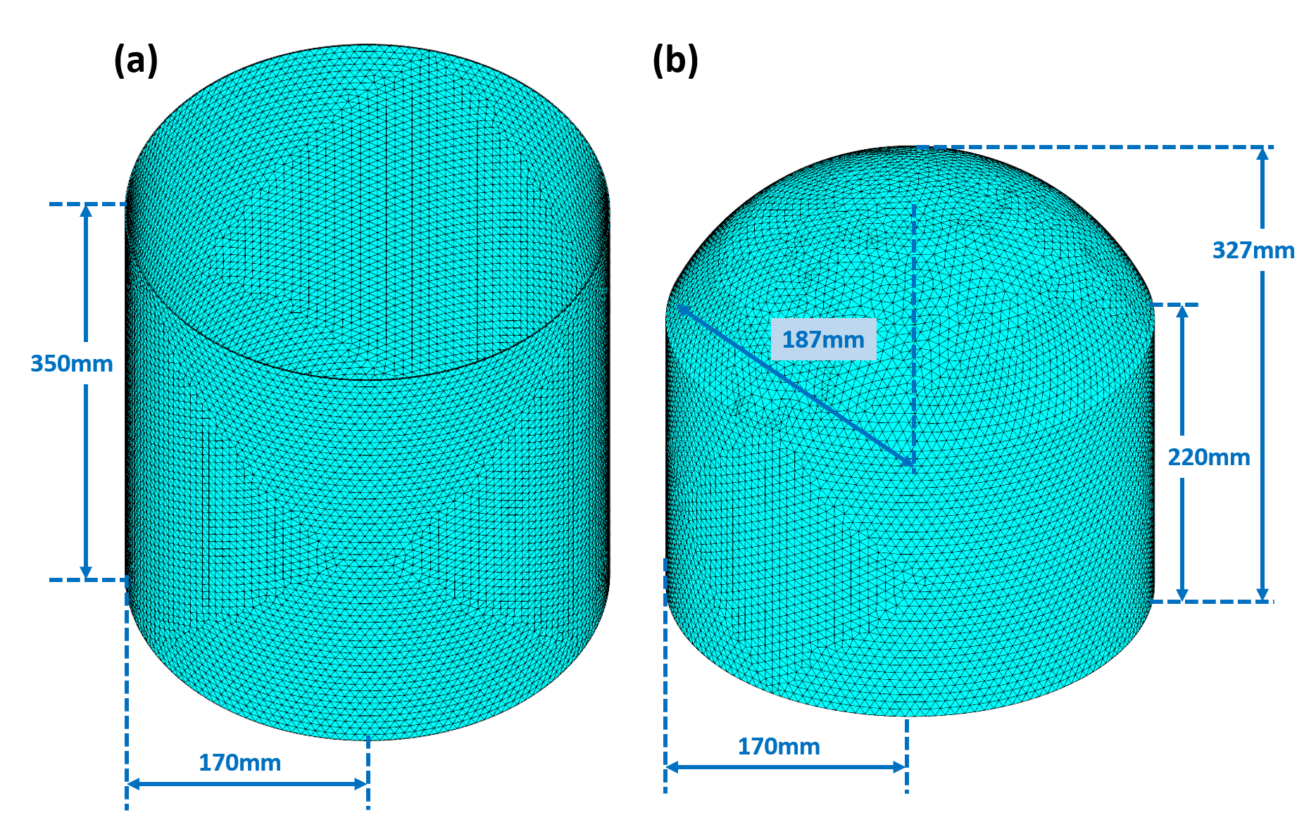
Figure 1 Cylinder and Helmet current-carrying surface.
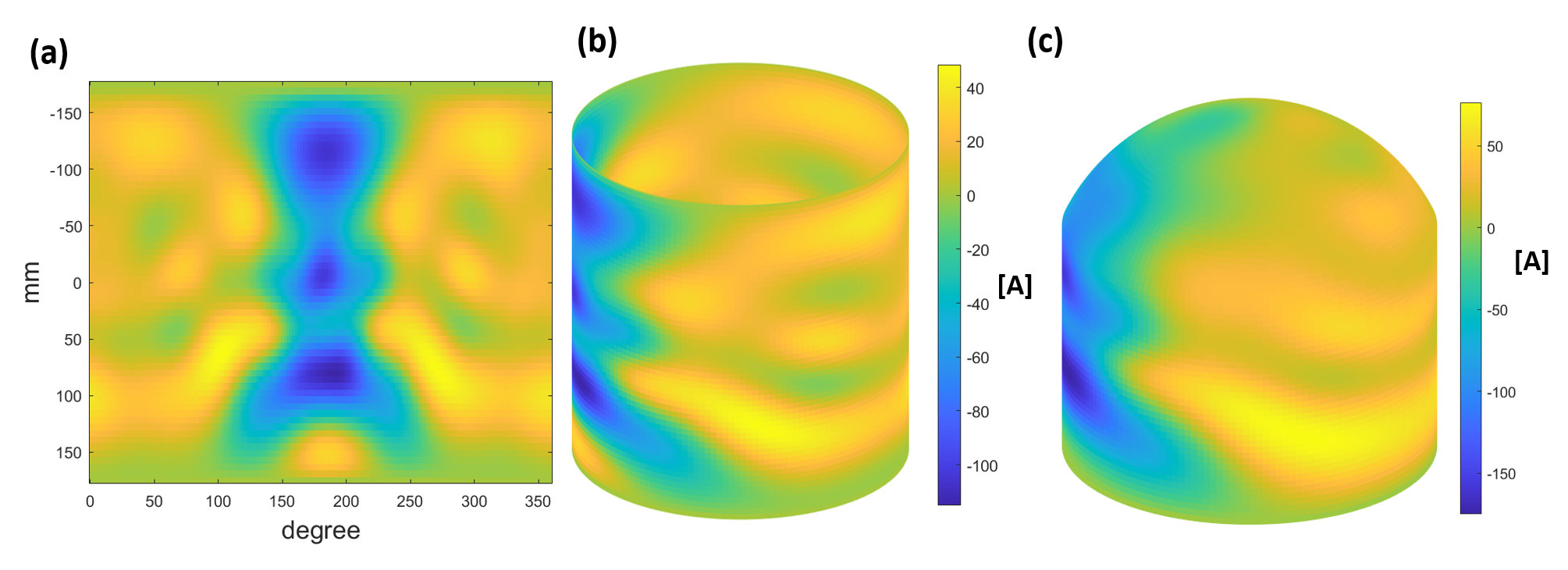
Figure 2 (a) is the expanded 2D optimized Stream Function of
350mm cylindrical current-carrying surface; (b) is the 3D Stream Function of
350mm cylindrical current-carrying surface; (c) is the optimized 3D Stream
Function of Helmet current-carrying surface. Color map is in the unit of
Ampere.
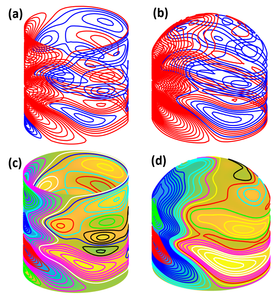
Figure 3 Discretized Coil of the optimized stream function for
(a) 350mm cylinder and (b) helmet as current-carry surface, respectively. Red
lines represent the wire direction counter-clockwise and blue lines represent
the wire direction clockwise. Grouped coil pattern for (a) 350mm cylinder and
(b) helmet, different colors are used for different groups.
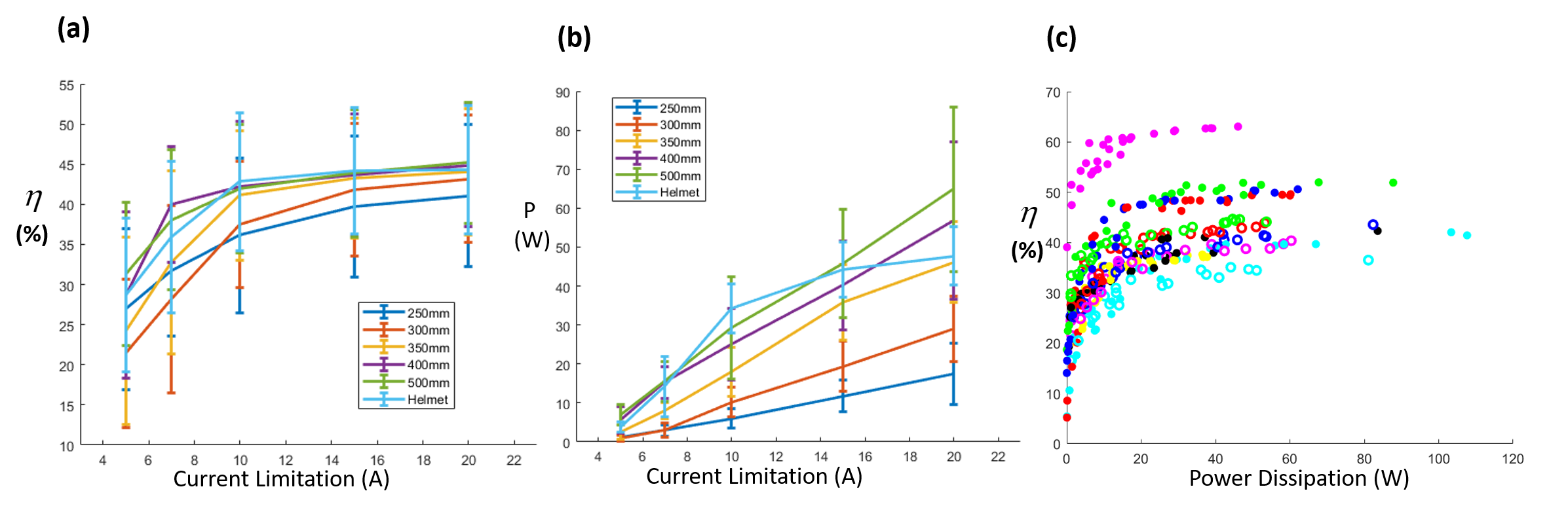
Figure 4 (a) Average and SD of Inhomogeneity reduction over
five current limitations (5A, 7A, 10A, 15A, and 20A) based on six current-carrying
surfaces (Cylinder with length 250mm, 300mm, 350mm, 400mm, 500mm, and Helmet) over
12-subjects; (b) Average and SD of power
dissipation over different current limitation over 12-subjects; (c) Inhomogeneity
reduction over power dissipation. Each color represents a subject and the points
consider five different current limitations based on six different surfaces.
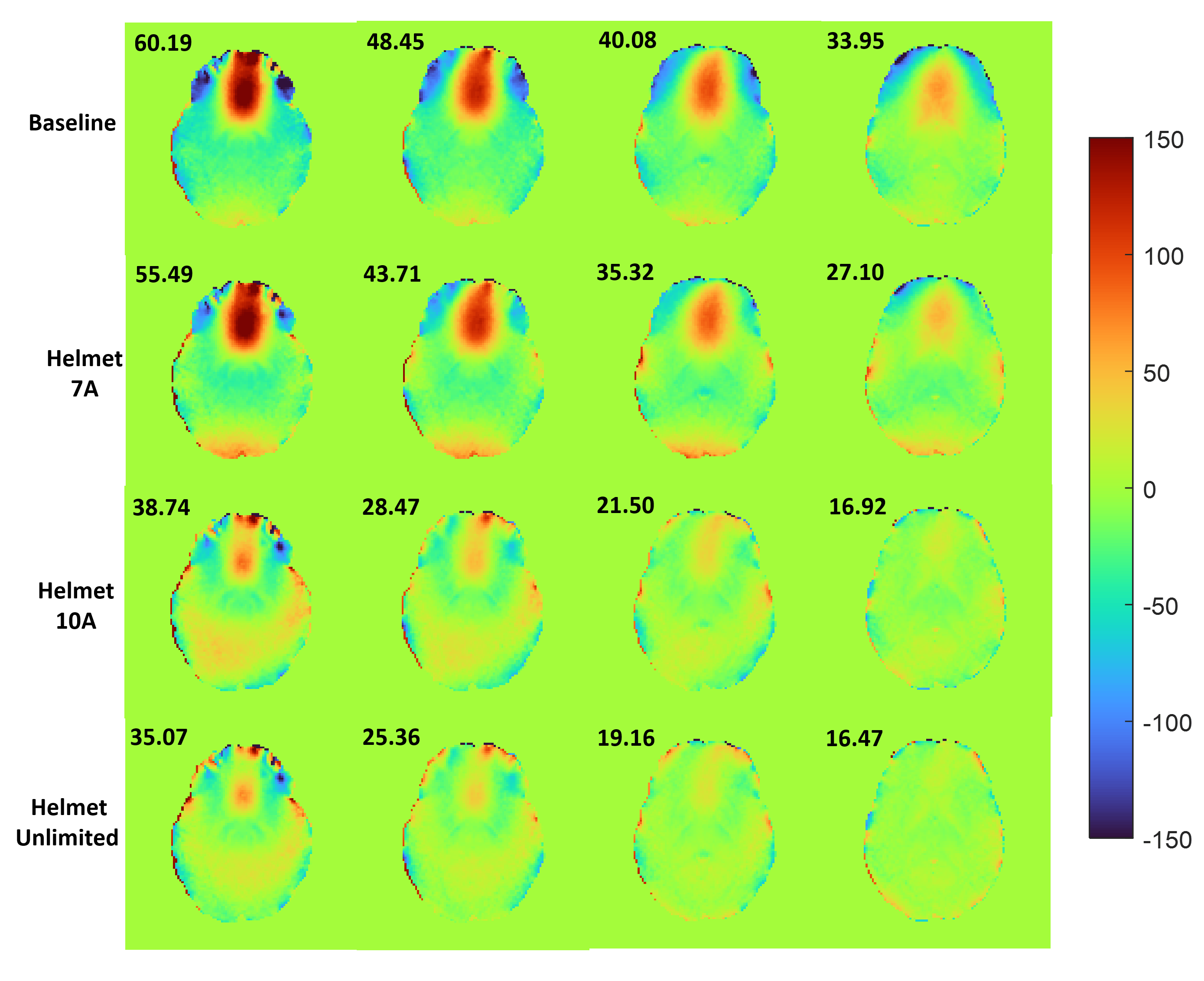
Figure 5 Baseline and shimmed field map under different
current limitation. From left to right are four slices in subject 2. From top
to bottom are baseline, and three different current limitation (7A, 10A,
unlimited).
DOI: https://doi.org/10.58530/2023/4418