4416
Multiphoton Parallel Transmission (MP-pTx)
John M Drago1,2,3, Bastien Guerin2,3, Stephen F Cauley2,3, and Lawrence L Wald2,3,4
1Electrical Engineering and Computer Science, Massachusetts Institute of Technology, Cambridge, MA, United States, 2Harvard Medical School, Boston, MA, United States, 3A. A. Martinos Center for Biomedical Imaging, Charlestown, MA, United States, 4Health Sciences and Technology, Massachusetts Institute of Technology, Cambridge, MA, United States
1Electrical Engineering and Computer Science, Massachusetts Institute of Technology, Cambridge, MA, United States, 2Harvard Medical School, Boston, MA, United States, 3A. A. Martinos Center for Biomedical Imaging, Charlestown, MA, United States, 4Health Sciences and Technology, Massachusetts Institute of Technology, Cambridge, MA, United States
Synopsis
Keywords: RF Pulse Design & Fields, Parallel Transmit & Multiband
We introduce multiphoton parallel transmission to mitigate nonuniform excitation in high-field MRI. Following an on-resonance birdcage subpulse, a multiphoton subpulse consisting of a single, off-resonance, high-frequency field from a birdcage coil, is supplemented with low-frequency parallel irradiation from a shim array. RF heating concerns are simplified compared to pTx, because only the birdcage coil produces significant SAR. Using a small-tip forward model, we optimize a nonconvex problem to find the amplitudes/phases of the low-frequency coils. Simulations demonstrate flip angle variation reduction across the brain ROI of 31.5% and NRMSE reduction of 42.0% compared to a conventional 7 T birdcage excitation.Introduction
Parallel transmission (pTx) is a well-known strategy to mitigate $$$B_1^+$$$ constructive and destructive interference in volume excitation coils at high field. However, clinical translation has been slowed by the high cost of RF excitation channels and complex SAR management/monitoring required to ensure safety. Both conventional excitation and pTx have also been supplemented by nonlinear encoding from shim arrays.1,2 In contrast, "multiphoton" or "side-band" excitations utilize an off-resonance RF field supplemented with a low-frequency, $$$\mathbf{\hat{z}}$$$-directed field at the frequency which completes energy conservation.3-8 Multiphoton excitations provide roughly 60% of the efficiency of an on-resonance excitation and were recently reintroduced with a classical Bloch equation description.9We demonstrate the ability of multiphoton excitations to mitigate flip angle inhomogeneities in high-field MRI when a birdcage coil (BC) is supplemented by oscillating $$$z$$$-fields from a multi-channel shim array. MP-pTx optimization resembles that used in conventional pTx with the crucial difference that the "parallel" part of the excitation is confined to low-frequency $$$\mathbf{\hat{z}}$$$-directed fields. This reduces the SAR concern to that of a conventional single-channel BC excitation.
Methods
Multiphoton Set-Up:Multiphoton excitation is achieved with a transverse, circularly-polarized $$$B_{1xy}$$$ pulse off-resonance by an amount $$$\Delta\omega_{xy}\;(\Delta\omega_{xy}\equiv\omega_0-\omega_{1xy})$$$. Significant transverse magnetization is created when an additional $$$\mathbf{\hat{z}}$$$-directed oscillating field is applied at $$$\omega_z$$$, with $$$k\omega_z=-\Delta\omega_{xy}$$$ for some integer $$$k$$$. For this work, we use $$$k=-1$$$ and $$$\Delta\omega_{xy}=2\pi(10\;\rm{kHz})$$$.
Optimization Formulation:
As shown in Figure 1, the first subpulse ("on-resonance BC") is a conventional BC excitation alone. The second subpulse uses an off-resonance BC pulse supplemented with oscillating shim and gradient fields, which spatially shape the transverse magnetization. We optimize coil current amplitudes/phases in the small-tip regime. Extending the excitation $$$k$$$-space framework10-12 to multiphoton excitation, we calculate a forward model similar to Han et al.13, although we substitute Bessel expansion for numerical integration and generalize to multiple, inhomogeneous $$$\mathbf{\hat{z}}$$$-directed fields.
The general solution to the small-tip Bloch equation in the Larmor rotating frame is:
$$M_r(\mathbf{r},T)=j\gamma{M_0}\int_{0}^{T}B_r(\mathbf{r},t)\exp\left(-j\gamma\int_{t}^{T}B_{z,\rm{eff}}(\mathbf{r},t^\prime)\,dt^\prime\right)\,dt\;,\label{eq:small-tip-bloch-soln}\tag{1}$$
where $$$B_r(\mathbf{r},t)$$$ is the complex-valued (transverse) magnetic field, which has time dependence when the RF is not at the Larmor frequency, and $$$B_{z,\rm{eff}}$$$ is the effective field in the $$$\mathbf{\hat{z}}$$$-direction:
$$B_{z,\rm{eff}}(\mathbf{r},t)=B_{1z}(\mathbf{r},t)+\mathbf{G}(t)\cdot\mathbf{r}\;.\tag{2}$$
Here, $$$B_{1z}(\mathbf{r},t)$$$ is the total $$$z$$$-component of the time-varying shim array fields, and $$$\mathbf{G}(t)\cdot\mathbf{r}$$$ is the time-varying gradient field. For both terms, we assume a cosine time dependence. In these experiments, we ignore main field inhomogeneities.
For each element in the shim array (with index $$$p$$$), $$$b_p$$$ denotes the magnitude of the shim current, $$$\varphi_p$$$ its phase, and $$$s_p(\mathbf{r})$$$ the unit-current $$$z$$$-component sensitivity profile. Similarly, $$$s_r(\mathbf{r})$$$ denotes the BC coil $$$B_1^+$$$ sensitivity with $$$b_r$$$ its complex phasor. Substituting these into Equation $$$\eqref{eq:small-tip-bloch-soln}$$$ and integrating $$$\cos(\omega_zt+\varphi_p)$$$ leads to our multiphoton forward model:
$$M_r(\mathbf{r},T)=j\gamma{M_0}\int_{0}^{T}s_r(\mathbf{r})b_re^{j\Delta\omega_{xy}t}e^{j\mathbf{k}(t)\cdot\mathbf{r}}\exp\left(\frac{j\gamma}{\omega_z}\sum_{p=1}^{P}s_p(\mathbf{r})b_p\left[\sin(\omega_zt+\varphi_p)-\sin(\omega_zT+\varphi_p)\right]\right)\;dt\;.\label{eq:fwd-model}\tag{3}$$
Here, $$$\mathbf{k}(t)\equiv\frac{\gamma}{\omega_z}\sum_{u=\{x,y,z\}}G_u\left[\sin(\omega_zt+\varphi_u)-\sin(\omega_zT+\varphi_u)\right]\mathbf{\hat{u}}$$$ denotes contributions from oscillating gradient fields, with $$$u$$$ specifying a specific coordinate axis and $$$G_u$$$ and $$$\varphi_u$$$ denoting magnitude and phase, respectively.
We time-discretize this forward model and formulate the pulse optimization problem as:
$$\arg\min_{\mathbf{d}}\lVert\left|\mathbf{m}_{\rm{targ}}\right|-\left|\boldsymbol{f}(\mathbf{d})+\mathbf{m}_{\rm{BC}}\right|\rVert_2\;,\tag{4}$$
where $$$|\cdot|$$$ denotes element-wise absolute value (similar to a magnitude least squares formulation14), $$$\mathbf{m}_{\rm{targ}}$$$ is a vector containing the desired magnetization over the ROI ($$$\sin10^{\circ}$$$ in this study), $$$\boldsymbol{f}$$$ is the multiphoton subpulse forward model operator (Equation $$$\eqref{eq:fwd-model}$$$), $$$\mathbf{m}_{\rm{BC}}$$$ is the magnetization from the on-resonance BC subpulse, and $$$\mathbf{d}$$$ is a vector of the design parameters, including phase and magnitude of the BC in each subpulse and the amplitudes and phases of the oscillating shim and gradient currents.
Pulse Optimization:
The optimization is nonconvex because the forward model is nonlinear with respect to the oscillating currents. We use a modified version of MATLAB’s genetic algorithm (20 generations, population of 1000) followed by 100 iterations of gradient descent (SQP algorithm) with constraints on maximum shim coil current (Amp-turns). We used a uniform flip angle target of $$$10^{\circ}$$$, $$$\Delta\omega_{xy}=2\pi(10\;\rm{kHz})$$$, individual subpulse duration of 2 ms, and numerical integration timestep of 0.1 $$$\mu$$$s. For $$$s_r(\mathbf{r})$$$, we use simulated 7 T $$$B_1^+$$$ BC maps in a realistic body model (Ansys, Inc., Canonsburg, PA, USA).15 For optimization, NRMSE was evaluated on a 354-point 3D brain mask with resolution of 15$$$\times$$$15$$$\times$$$20 mm (AP$$$\times$$$LR$$$\times$$$SI). The $$$s_p(\mathbf{r})$$$ were simulated using Biot-Savart maps for 32- or 48-channel shim arrays.16,17 Optimized pulse performance at higher resolution was assessed after 100 additional iterations of gradient descent by Bloch simulation (2$$$\times$$$10 mm in-plane/through-plane, 19478 points).
Results
Figure 3 shows a scatter plot of solutions comparing NRMSE for different peak shim coil current constraints. Figure 4 shows the magnetization from an optimized pulse with a shim current constraint of 50 Amp-turns. Figure 5 shows a similar optimization using only gradient coils (no shim array). With the shim array and gradients, MP-pTx reduced brain ROI NRMSE by 42.0% and flip angle variation by 31.5% compared to a conventional birdcage-only excitation.Discussion
We introduce MP-pTx to mitigate flip angle inhomogeneity at 7 T and validated its performance using Bloch simulations. The optimization procedure rapidly evaluates the forward model, but the nonconvex nature of the problem reduces optimization speed and robustness requiring further evaluation. Currently, the method evaluates non-selective excitations and needs generalization to slice-selective excitations.Acknowledgements
The authors thank Jason Stockmann and Ehsan Kazemivalipour for helpful discussions. This work was supported by NIH grants P41EB030006, F30MH129062, and T32GM144273.References
1 B. Guerin, E. Milshteyn, L. L. Wald, and J. Stockmann, “Improvements in flip-angle uniformization at 7 Tesla using an integrated RF/B0 shim array coil and composite pulses,” in Proceedings of the Annual Meeting of ISMRM (online), #613, 2020.2 M. Vinding, T. Lund, J. Stockmann, and B. Guerin, “INSTANT (INtegrated Shimming and Tip-Angle NormalizaTion): 3D flip-angle mitigation using joint optimization of RF and shim array currents,” in Proceedings of the Annual Meeting of ISMRM (online), #612, 2020.
3 A. Abragam, The Principles of Nuclear Magnetism. Oxford University Press, 1961.
4 D. G. Gold and E. L. Hahn, “Two-photon transient phenomena,” Physical Review A, vol. 16, pp. 324–326, 1977.
5 R. Boscaino and G. Messina, “Double quantum coherent transients in a two-level spin system: A vectorial model,” Physica B+C, vol. 138, pp. 179–187, 1986.
6 C. A. Michal, “Nuclear magnetic resonance noise spectroscopy using two-photon excitation,” Journal of Chemical Physics, vol. 118, no. 8, pp. 3451–3454, 2003.
7 P. T. Eles and C. A. Michal, “Two-photon excitation in nuclear magnetic and quadrupole resonance,” Progress in Nuclear Magnetic Resonance Spectroscopy, vol. 56, no. 3, pp. 232–246, 2010.
8 D. O. Brunner, M. Pavan, B. Dietrich, D. L. Rothman, A. Heller, and K. P. Pruessmann, “Sideband Excitation for Concurrent RF Transmission and Reception,” in Proceedings of the Annual Meeting of ISMRM, #625, 2011.
9 V. Han and C. Liu, “Multiphoton magnetic resonance in imaging: A classical description and implementation,” Magnetic Resonance in Medicine, vol. 84, no. 3, pp. 1184–1197, 2020.
10 J. Pauly, D. Nishimura, and A. Macovski, “A k-space analysis of small-tip-angle excitation,” Journal of Magnetic Resonance (1969), vol. 81, pp. 43–56, 1989.
11 C. Y. Yip, J. A. Fessler, and D. C. Noll, “Iterative RF pulse design for multidimensional, small-tip-angle selective excitation,” Magnetic Resonance in Medicine, vol. 54, no. 4, pp. 908–917, 2005.
12 W. Grissom, C. Y. Yip, Z. Zhang, V. A. Stenger, J. A. Fessler, and D. C. Noll, “Spatial domain method for the design of RF pulses in multicoil parallel excitation,” Magnetic Resonance in Medicine, vol. 56, no. 3, pp. 620–629, 2006.
13 V. Han, J. Chi, and C. Liu, “Pulsed Selective Excitation in Multiphoton MRI,” in Proceedings of the Annual Meeting of ISMRM, #451, 2022.
14 K. Setsompop, L. L. Wald, V. Alagappan, B. A. Gagoski, and E. Adalsteinsson, “Magnitude least squares optimization for parallel radio frequency excitation design demonstrated at 7 tesla with eight channels,” Magnetic Resonance in Medicine, vol. 59, no. 4, pp. 908–915, 2008.
15 E. Kazemivalipour, L. L. Wald, and B. Guerin, “Comparison of simulated parallel transmit head arrays at 7T using excitation uniformity, local, and global SAR,” in Proceedings of the Annual Meeting of ISMRM, #5048, 2022.
16 J. P. Stockmann, T. Witzel, B. Keil, J. R. Polimeni, A. Mareyam, C. Lapierre, K. Setsompop, and L. L. Wald, “A 32-channel combined RF and B0 shim array for 3T brain imaging,” Magnetic Resonance in Medicine, vol. 75, no. 1, pp. 441–451, 2016.
17 C. Juchem, T. W. Nixon, S. McIntyre, V. O. Boer, D. L. Rothman, and R. A. De Graaf, “Dynamic multi-coil shimming of the human brain at 7 T,” Journal of Magnetic Resonance, vol. 212, no. 2, pp. 280–288, 2011.
Figures
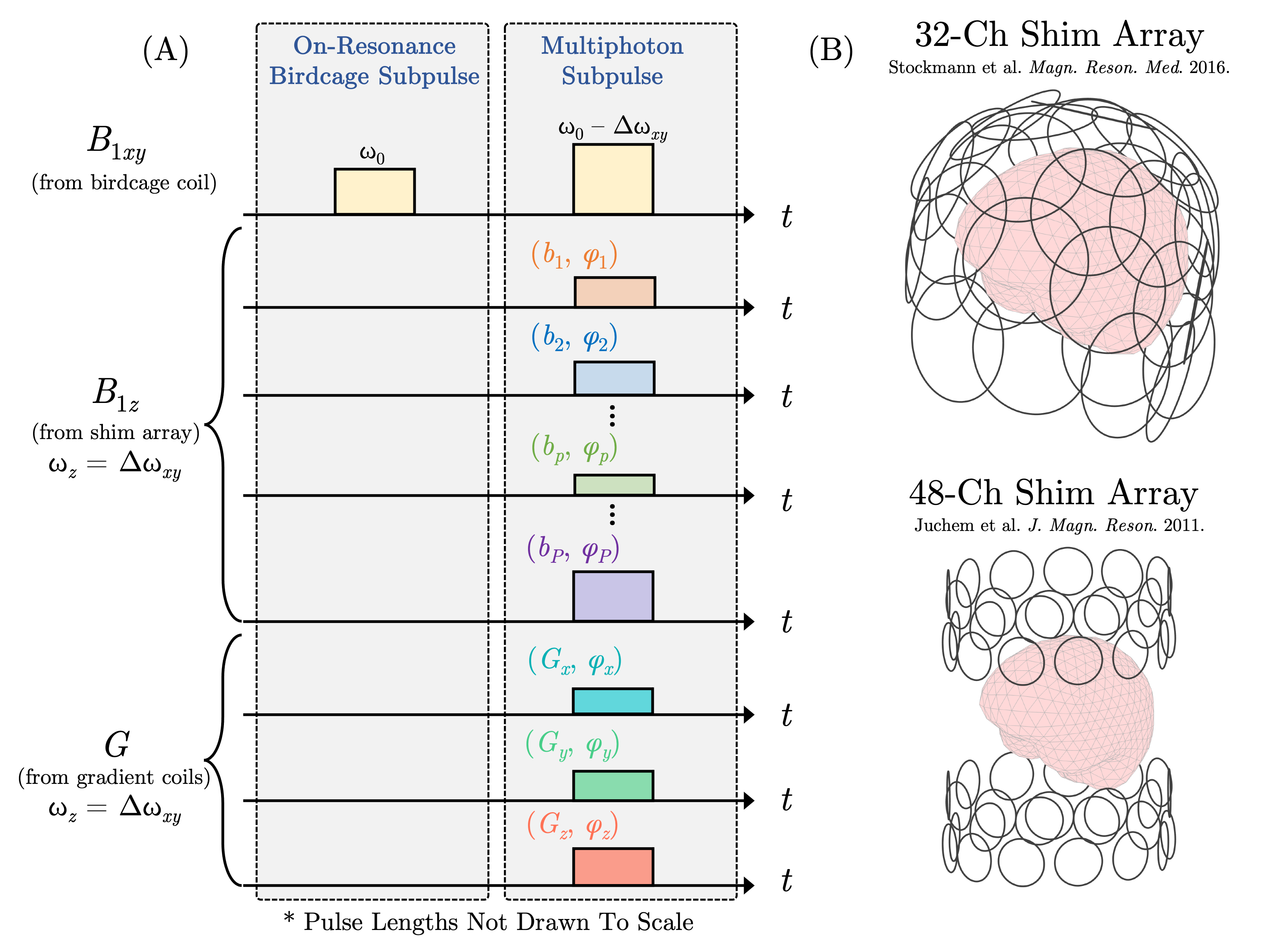
MP-pTx excitation scheme. (A) The MP-pTx excitation consists of two subpulses. An on-resonance birdcage subpulse from the birdcage coil generates inhomogeneous transverse magnetization. During the multiphoton subpulse, two fields are needed to generate significant transverse magnetization – an off-resonance RF birdcage hard pulse and a low-frequency sinusoidal $$$\mathbf{\hat{z}}$$$-directed field from the shim array and gradient coils. (B) The 32- and 48-channel shim arrays are shown.
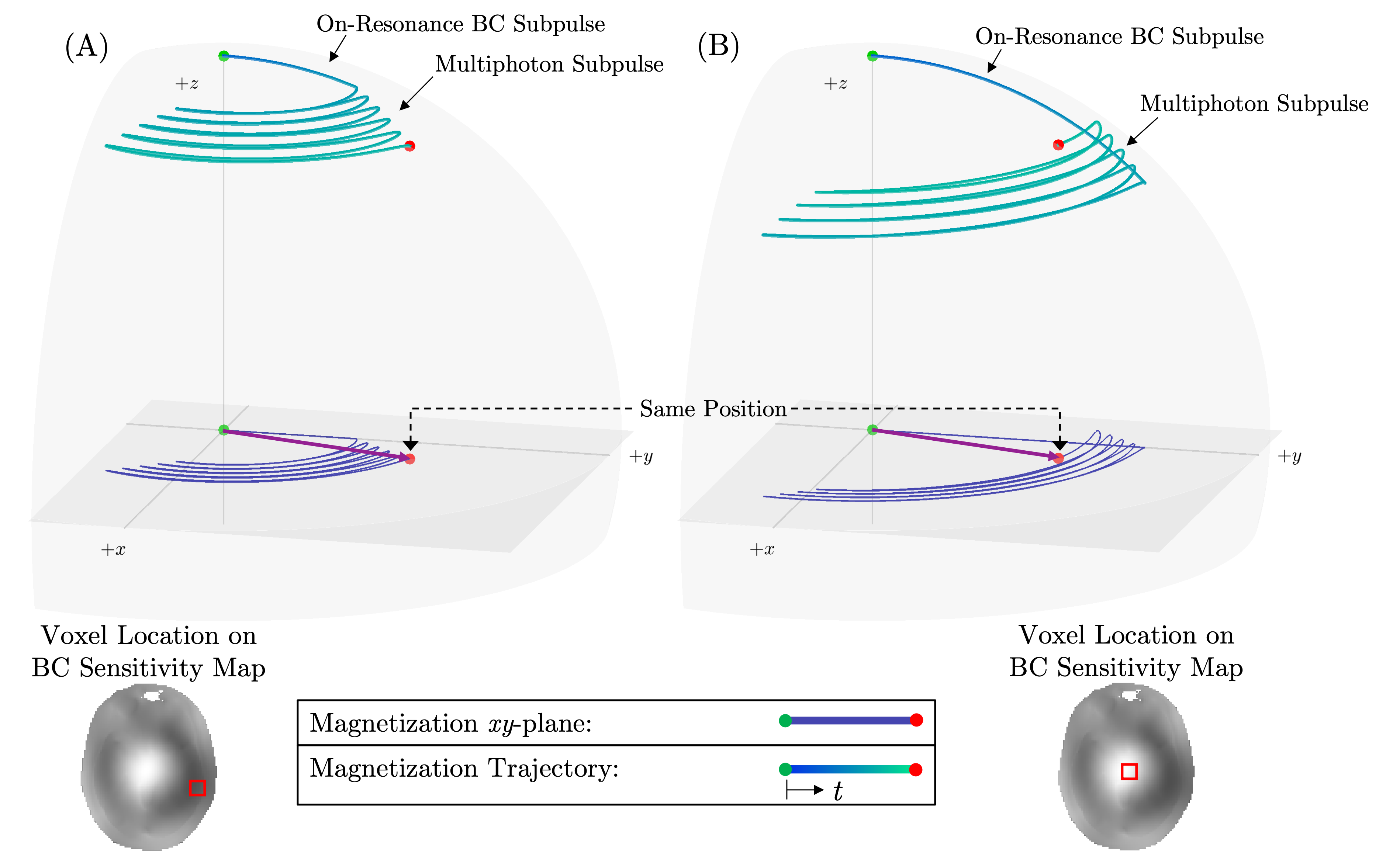
MP-pTx magnetization trajectory in Larmor frame. Illustrative demonstrations of magnetization trajectories at two marked locations within the head for the combined on-resonance birdcage excitation subpulse and the multiphoton pulse. (A) For this voxel location, the birdcage coil under-tips, and the multiphoton subpulse brings the excitation to the correct transverse magnetization. (B) For this voxel location, the multiphoton subpulse must reduce the flip angle.
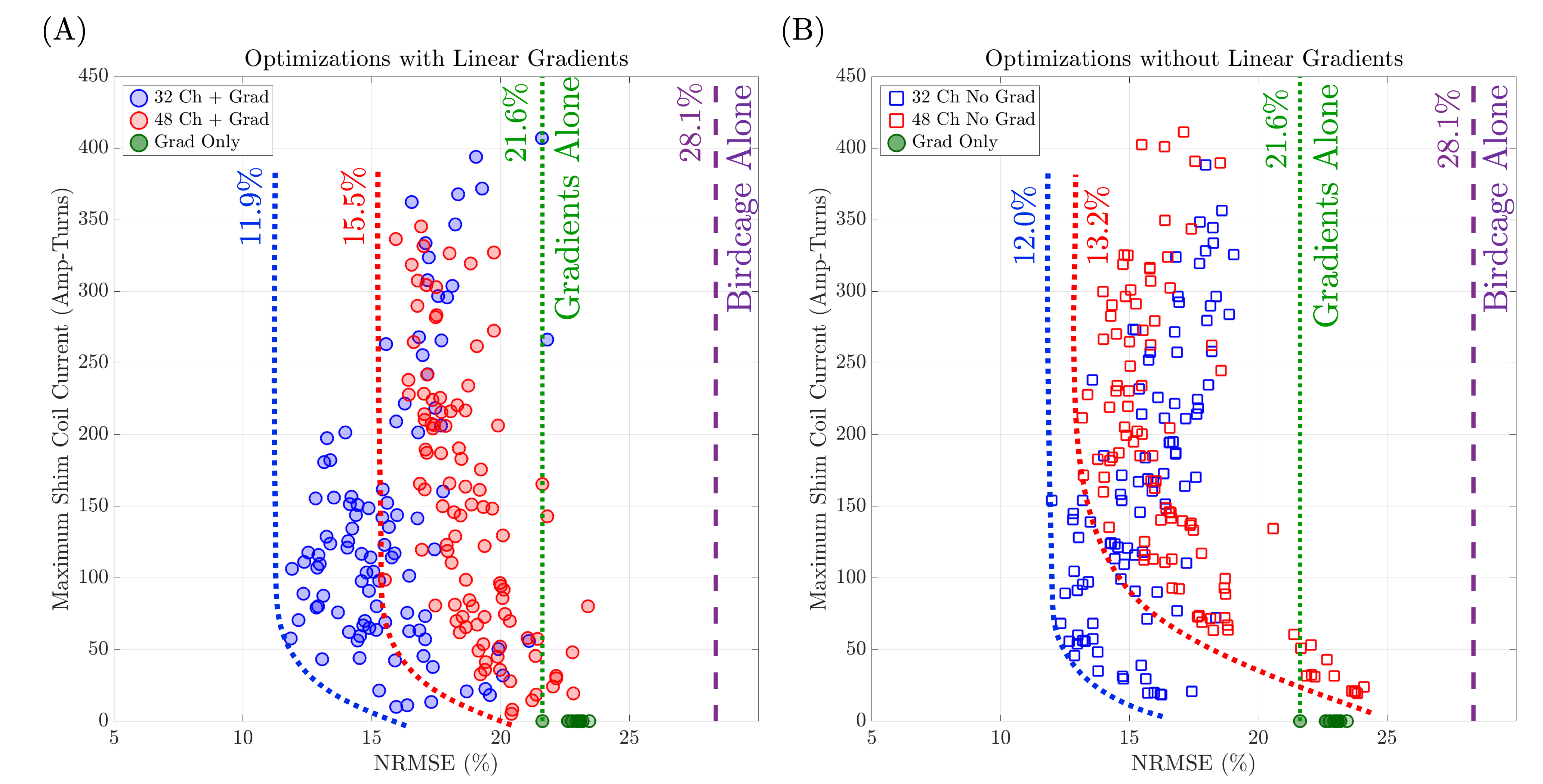
Possible solutions from the genetic algorithm-based optimization procedure for a uniform magnitude target with different maximum shim coil current constraints. The dotted red and blue lines denote approximate operational trade-off L-curves for the two arrays. The dashed purple line denotes the ROI’s NRMSE from excitation with a conventional on-resonance birdcage pulse. (A) Optimization using both shim coils and gradients. (B) Optimization with only shim coils (no gradients).
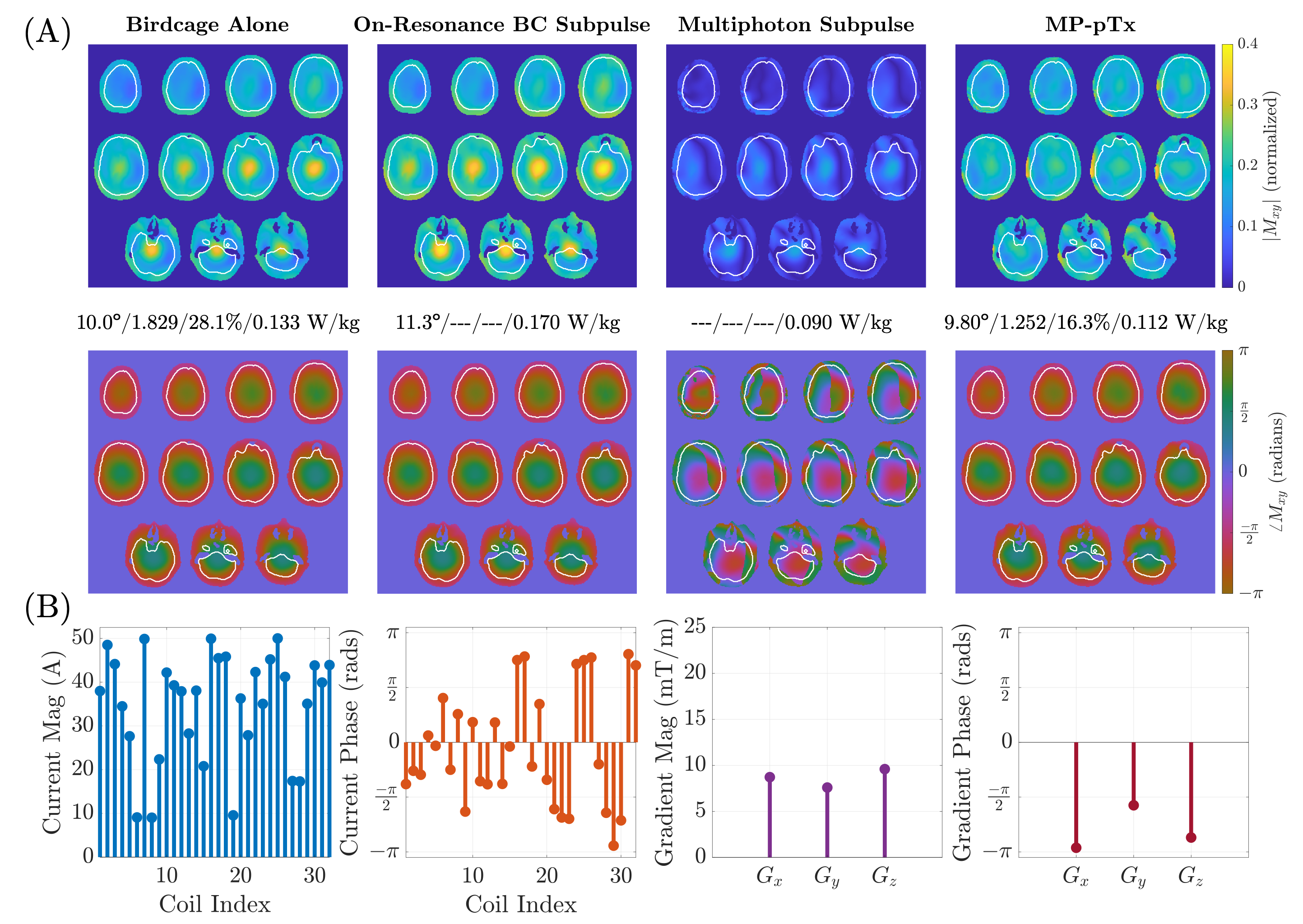
Results from MP-pTx optimization process for the 32-channel shim array with linear gradients and 50 Amp-turn current constraint. (A) Magnetization profiles in columns from L-to-R: (1) excitation with birdcage alone, (2) the on-resonance BC subpulse, (3) the MP subpulse, (4) the full pulse (column 2 followed by column 3). The metrics are reported in the following form: flip angle (degrees)/mean-normalized maximum-minimum flip angle difference/NRMSE (%)/Global SAR (W/kg). Optimization was performed only over brain ROI. (B) The optimized design parameters.
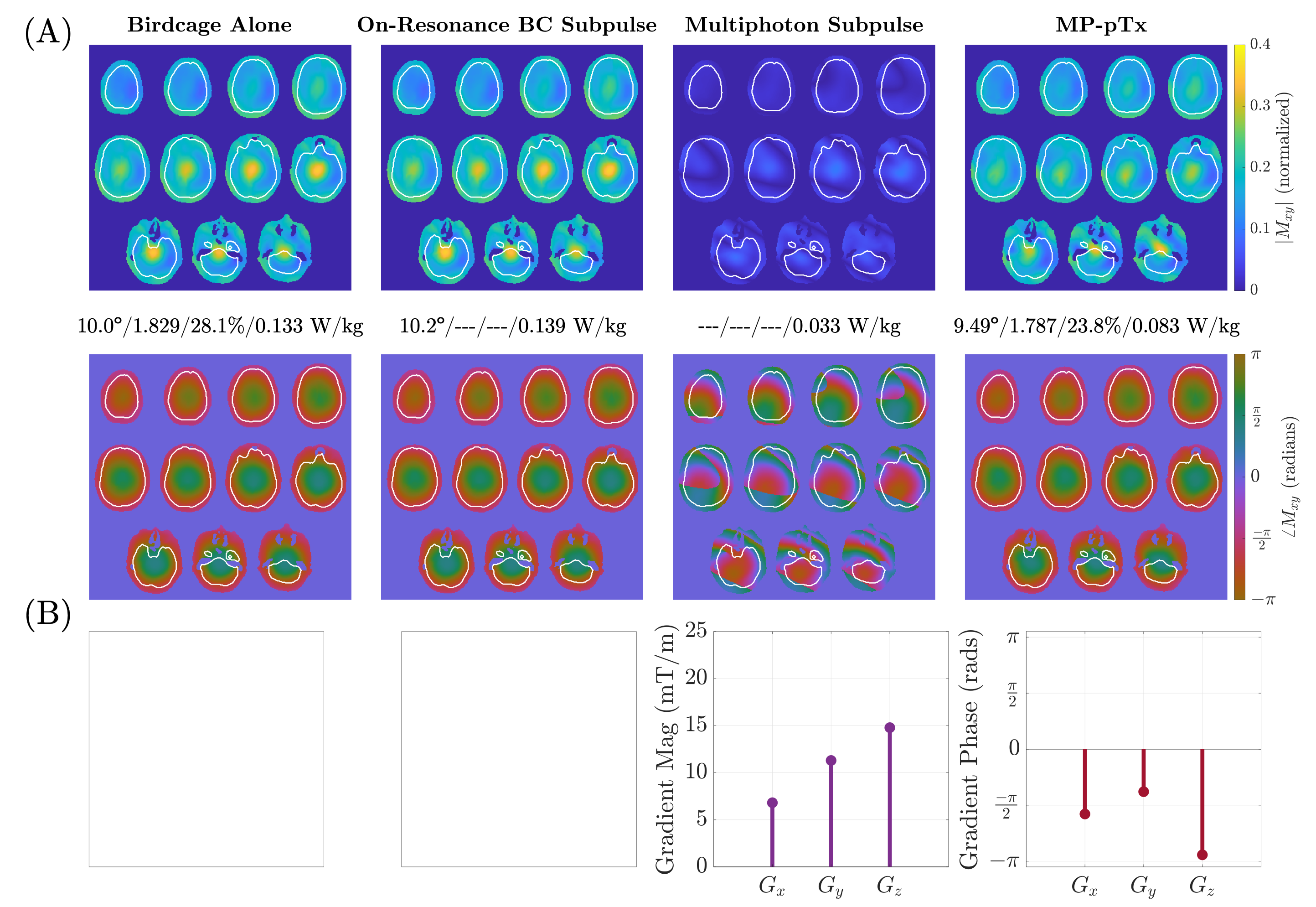
Results from MP-pTx optimization process with linear gradients alone. (A) Magnetization profiles in columns from L-to-R: (1) excitation with birdcage alone, (2) the on-resonance BC subpulse, (3) the MP subpulse, (4) the full pulse (column 2 followed by column 3). The metrics are reported in the following form: flip angle (degrees)/mean-normalized maximum-minimum flip angle difference/NRMSE (%)/Global SAR (W/kg). Optimization was performed only over brain ROI. (B) The optimized design parameters.
DOI: https://doi.org/10.58530/2023/4416