4412
RF mode switching based Tx coil system for B1+ homogeneity mitigation at 7T: basic concept and preliminary study1Human Brain Research Center, Graduate School of Medicine, Kyoto University, Kyoto, Japan, 2National Institute for Physiological Sciences, Okazaki, Japan, 3University of Queensland, Brisbane, Australia
Synopsis
Keywords: RF Arrays & Systems, RF Arrays & Systems, RF-mode, non-pTx
To mitigate B1 inhomogeneity problems in ultra-high-field MRI, we proposed RF-mode switching technique which doesn’t need an expensive parallel transmit (pTx) system. As a preliminary study, we developed an RF-switching circuit (one of the main parts of the system) and validated its function through phantom experiments. The results showed that the switching function works well, although a certain degree of power-loss was observed both at bench (< -1dB) and on the images. We have re-designed a new switching circuit and will continue to the development to demonstrate this technique at a fraction of the cost of a pTx system.Background
Although ultra-high field (UHF) MRI offers many opportunities by virtue of its high SNR and strong contrast, B1 inhomogeneity degrades image quality and can limit its usage in clinics and research. To mitigate this problem, many studies have proposed [ex. 1,2]. In 2016, Cloos et al. [3] proposed that complementary RF profiles, such as the circularly polarized (CP) and gradient modes, can be interwoven in a fingerprinting scan to overcome B1 artifacts. Although this idea was demonstrated using a pTx system, it should be possible to achieve the same functionality with a much simpler and cheaper setup. The goal of our study is to construct a dedicated Tx coil system with this RF-mode-switching function on our non-pTx 7T scanner to demonstrate this technique at a fraction of the cost of a pTx system. We introduce the basic concept and show preliminary experimental results.Methods and Materials
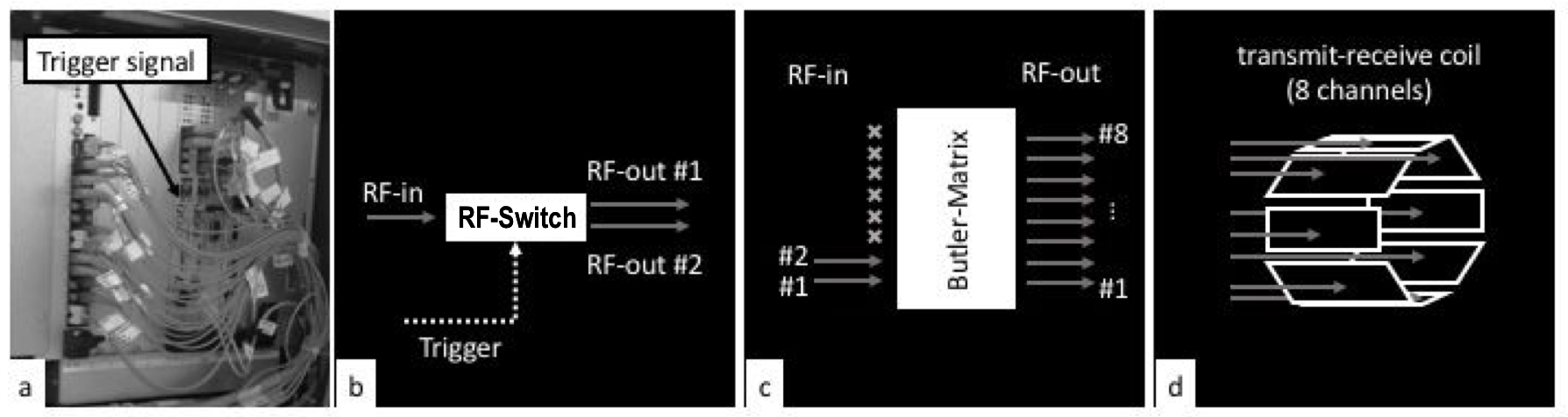
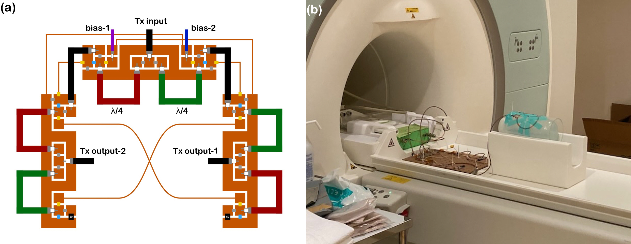
Figure 1 shows the basic design of the RF-mode-switching based transmit (Tx) system. It consists of three devices connected in series: an RF-switching circuit (SC), a Butler matrix [4], and an 8ch Tx coil. The Tx input to SC flows to either of the two output ports depending on the TTL signal from the system cabinet whose timing and duration are specified in our sequence code. And then, it will be divided into eight with hybrid couplers in the Butler matrix with phase shifting for CP (if the current passes port-1) or gradient (port-2) mode to transfer into the 8ch Tx coil.As a preliminary study, we developed a prototype of SC (Fig.2a) and validated its function with a 2ch Tx/Rx phased array coil. SC consists of three similar switch circuits (one main and two sub-circuits) controlled with two bias inputs. Each circuit has two quarter-wavelength coax cables [5]. When a bias current is applied from the bias-1 (or 2) line, the Tx power from the main circuits will flow through the right (or left) sub-circuit and out to the Tx-output-1 (or 2). At the same time, the other coil is terminated with 50ohm load. The S12 of SC was about -1 dB.
Validation exams were carried out on a Magnetom 7T-MRI system (Siemens, Erlangen, Germany) (Fig.2b). The Tx input port and one of the two bias lines of SC were connected to an interface box which provided 1ch Tx and bias current from the patient table connector and received Rx signals through SC (in the future TR switches will be moved closer to toil past the SC). The two output ports of SC were hooked up to the 2ch Tx/Rx phased-array coil with a bottle phantom filled with 0.5% NaCl solution. Phantom images were obtained using a gradient-echo (GRE) sequence with a small flip-angle (4V Tx voltage ) and compared with ones measured without SC between the interface box and the coil. To calculate the SNR-map of each image, two GRE images were obtained one with 0V Tx voltage and the other with 4V.
Results
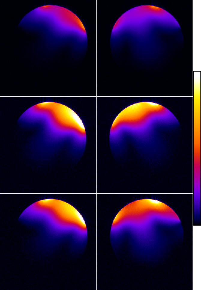
Figure 3 shows the SNR maps obtained from the two coil elements with/without SC. Similar coil sensitivity patterns between maps with and without SC indicate that SC effectively delivers the Tx current to only one of the two channels of the coil and that the other coil is properly terminated with a 50Ohm load (or else it would couple). However, more than twice the difference in the SNR between them suggests a certain degree of power-loss existed in the present SC.Discussion
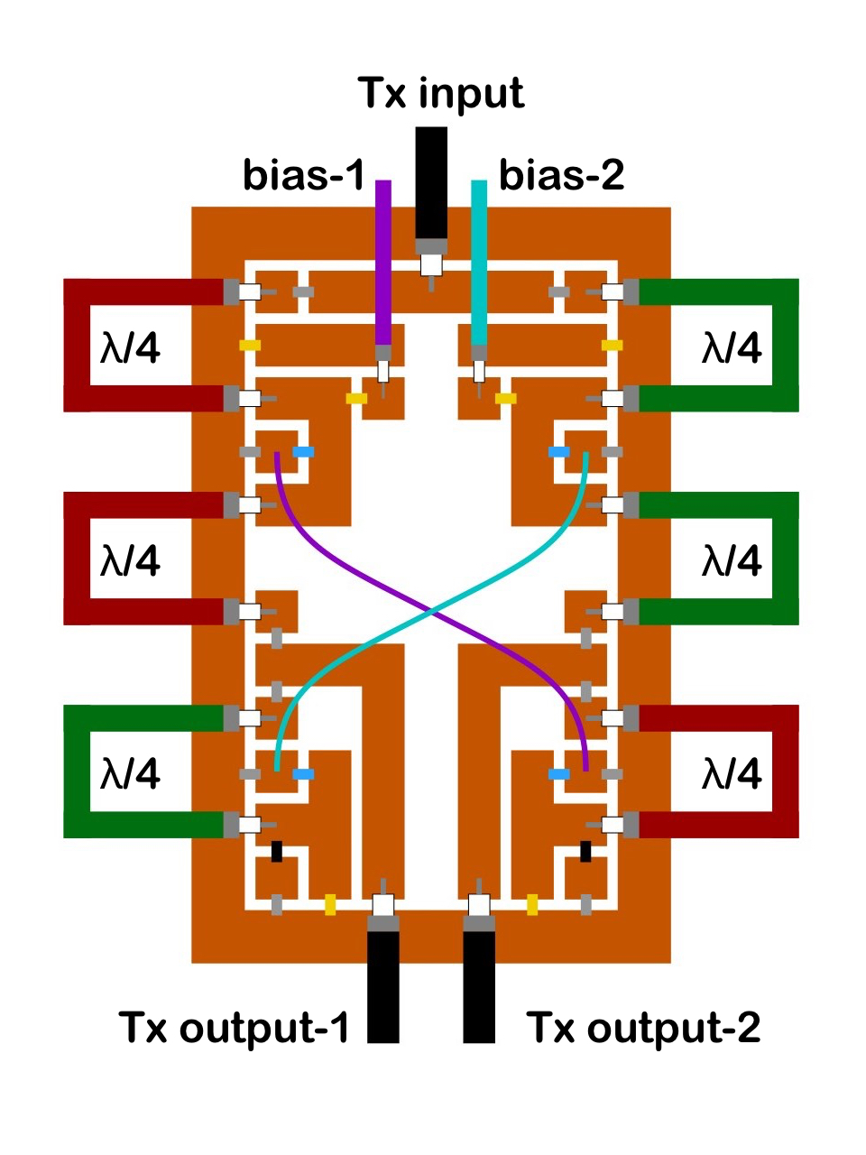
Despite plenty of studies aiming to solve the B1 inhomogeneity problem in UHF-MRI, only adiabatic pulses are used universally available. Because the RF-mode switching technique can be made affordably and doesn’t need a pTx system, it could be accessible to wider audiences.The RF switch circuit we produced in this preliminary study showed the switching function works well, although we observed slightly more power-loss than expected. Probably this loss was caused by insufficient tuning of the circuits, cheap components on this test board, and redundancy in the design as a prototype. Since the received MR signal also pass-through SC, the observed loss in SNR is a combination form losses in transmit power and added noise in the receive chain. To reduce the transmit losses, we have designed a compact and more efficient switching circuit on a single PCB (Fig. 4) and will produce it at the next step. In addition, we will move the preamplifiers closer to the coil behind the SC.
Except for SC, there are several devices we will have to develop for an RF-mode switching system with optimal performance, such as a bias current switching circuit, the Butler matrix, an 8ch Tx coil, and an Rx-only phased-array coil. The bias current switching circuit is a part of SC that provides the current to one of the two bias inputs of SC based on the TTL signal from the cabinet. [MC1]And cheap components on this test board.
Conclusion
To mitigate the B1 inhomogeneity problem at non-pTx UHF-MRI, we proposed the RF-mode switching system. Here, we built an RF switching circuit as a preliminary study and demonstrated the usefulness of the circuit.Acknowledgements
This work was supported by JSPS KAKENHI (Grant Nos. JP19H03601).References
1. Green EM, B1 insensitive techniques for ultra-high field magnetic resonance imaging, PhD Thesis, http://hdl.handle.net/11343/311718 (2021)
2. Ladd ME, et al., Pros and cons of ultra-high-field MRI/MRS for human application., Prog Nucl Magn Reson Spectrosc 109:1–50 (2018)
3. Cloos MA, et al., Multiparametric imaging with heterogeneous radiofrequency fields. Nat Commun 7:12445. (2016)
4. Alagappan V, et al., Degenerate Mode Band-Pass Birdcage Coil for Accelerated Parallel Excitation, Magn. Reson. Med., 57:1148–1158 (2007)
5. Ji Y, et al., High peak and high average radiofrequency power transmit/ receive switch for thermal magnetic resonance, Magn. Reson. Med., 80:2246–2255 (2018)
Figures