4406
Design of a universal RF-shimming drive mode for head and neck imaging at 7 Tesla using a 16-channel pTx array1A. A. Martinos Center for Biomedical Imaging, Department of Radiology, Massachusetts General Hospital, Charlestown, MA, United States, 2Harvard Medical School, Boston, MA, United States, 3Erwin L. Hahn Institute for MRI, University Duisburg-Essen, Essen, Germany, 4High-Field and Hybrid MR Imaging, University Hospital Essen, Essen, Germany, 5Harvard-MIT Division of Health Sciences Technology, Cambridge, MA, United States, 6Institute of Medical Physics and Radiation Protection, Department of Life Science Engineering, Mittelhessen University of Applied Sciences, Giessen, Germany, 7Center for Mind, Brain and Behavior (CMBB), Philipps-University Marburg, Marburg, Germany
Synopsis
Keywords: RF Pulse Design & Fields, RF Pulse Design & Fields
We calculate “universal” RF-shimming excitations that provide maximum B1+ coverage and homogeneity across the brain & c-spine using a patient-friendly 16-channel pTx array. We simulated three body models and three z-positions to ensure robustness to both B1+ and SAR variation across a range of head/neck sizes and shapes (universal design). We provide two solutions, both of which may be saved on the scanner: a low-SAR solution that improves flip-angle uniformity by 13% compared to the BC mode excitation (same SAR) and a high-SAR excitation that improves flip-angle non-uniformity by 25% at the cost of a 2x local SAR increase.Introduction
May et al. have introduced a patient-friendly 16-channel pTx coil for 7 Tesla imaging of the head and neck (64 receive channels)1. Coverage of the neck region opens the door for detailed examinations of the c-spine, while the large field-of-view of the coil allows concurrent brain imaging, which is useful, for example, for studying the functional connectivity of the brain and c-spine. In this work, we design RF-shimming excitations with optimal B1+ coverage and uniformity in both the brain and c-spine. We perform these designs for multiple body models and positions in an attempt to yield excitation modes that are “universal” both in B1+ and SAR and are, therefore, broadly applicable to subjects with varying head/neck geometries.Methods
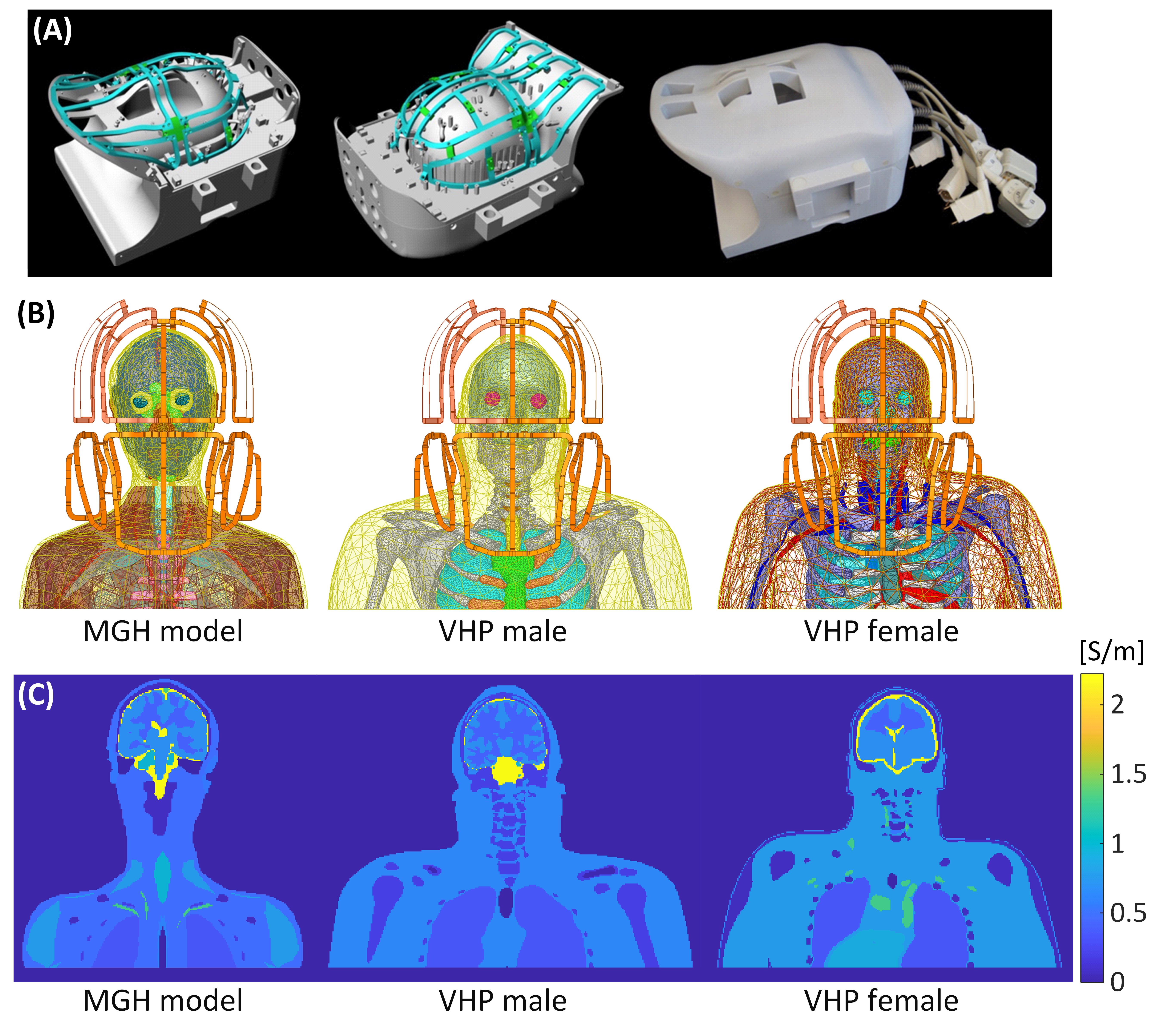
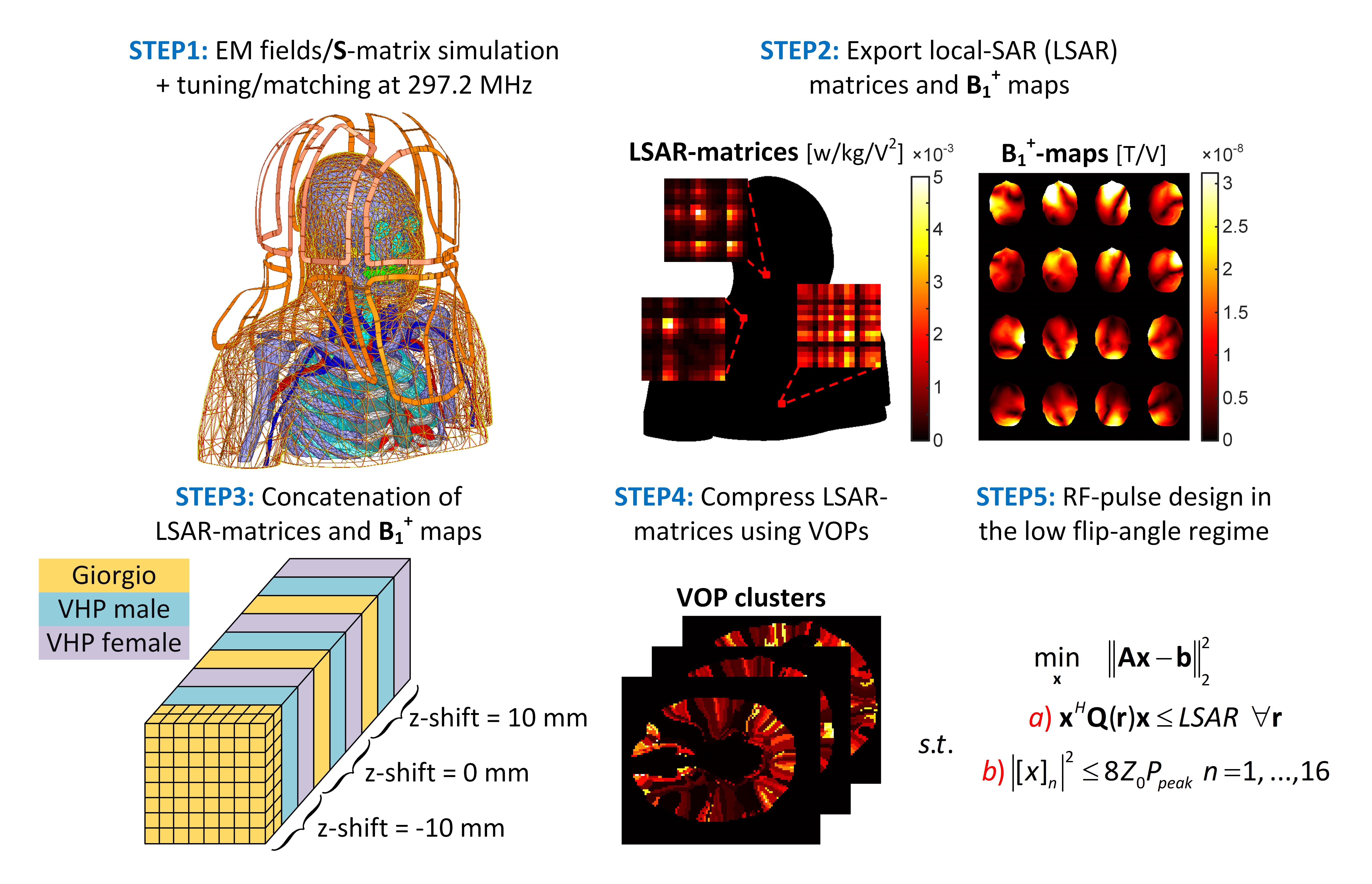
Figure 1A shows the CAD model of May et al. 16-channel pTx array for combined head/neck MRI at 7T1. We simulated the array loaded with three different detailed human head/shoulder models (MGH model2,3, VHP male4, and VHP female5), as shown in Figures 1B-C. Each body model was placed at three different z-positions: -10mm, 0mm (eyes at isocenter), and 10mm, to build in robustness with respect to subject motion. Figure 2 shows the flowchart of the RF pulse design. EM simulations were carried out using ANSYS Electronics (ANSYS Inc., Canonsburg, PA), as was circuit co-simulation, which was employed for fast tuning, matching and decoupling of the lumped-elements (reflection coefficient <-20dB & coupling coefficient <-10dB).For each body model, we extracted the E-fields and B1+-maps generated by each channel on a 2-mm isotropic image grid and then concatenated them along the z-direction (total of 146×286×2079 voxels). Therefore, the concatenated fields contain information about 3 (# of models) × 3 (# of z-positions) = 9 EM simulations. We then compressed the concatenated 10g-averaged Q-matrices6 using the virtual observation points (VOPs)7 strategy followed by the so-called “generalized VOP” algorithm (gVOP)8 that we report on a separate abstract (SAR overestimation factor = 7.5×10⁻⁴ W/kg/V2, 764 VOPs for all body models/positions).
We designed RF-shimming pulses (target flip-angle of 10°, can be scaled to any desired target) in the brain-spine masks of the concatenated body models. The goal of this pulse design strategy is to yield pulses that are broadly applicable in the clinical setting in a “plug-and-play” manner. For SAR reporting, we simulate 5-lobe slice-selective sincs with a 2-ms duration and 100% duty cycle. We used magnitude least-squares (MLS)9 optimizations to design RF pulses while constraining the peak voltage per channel to below 400V10.
Results
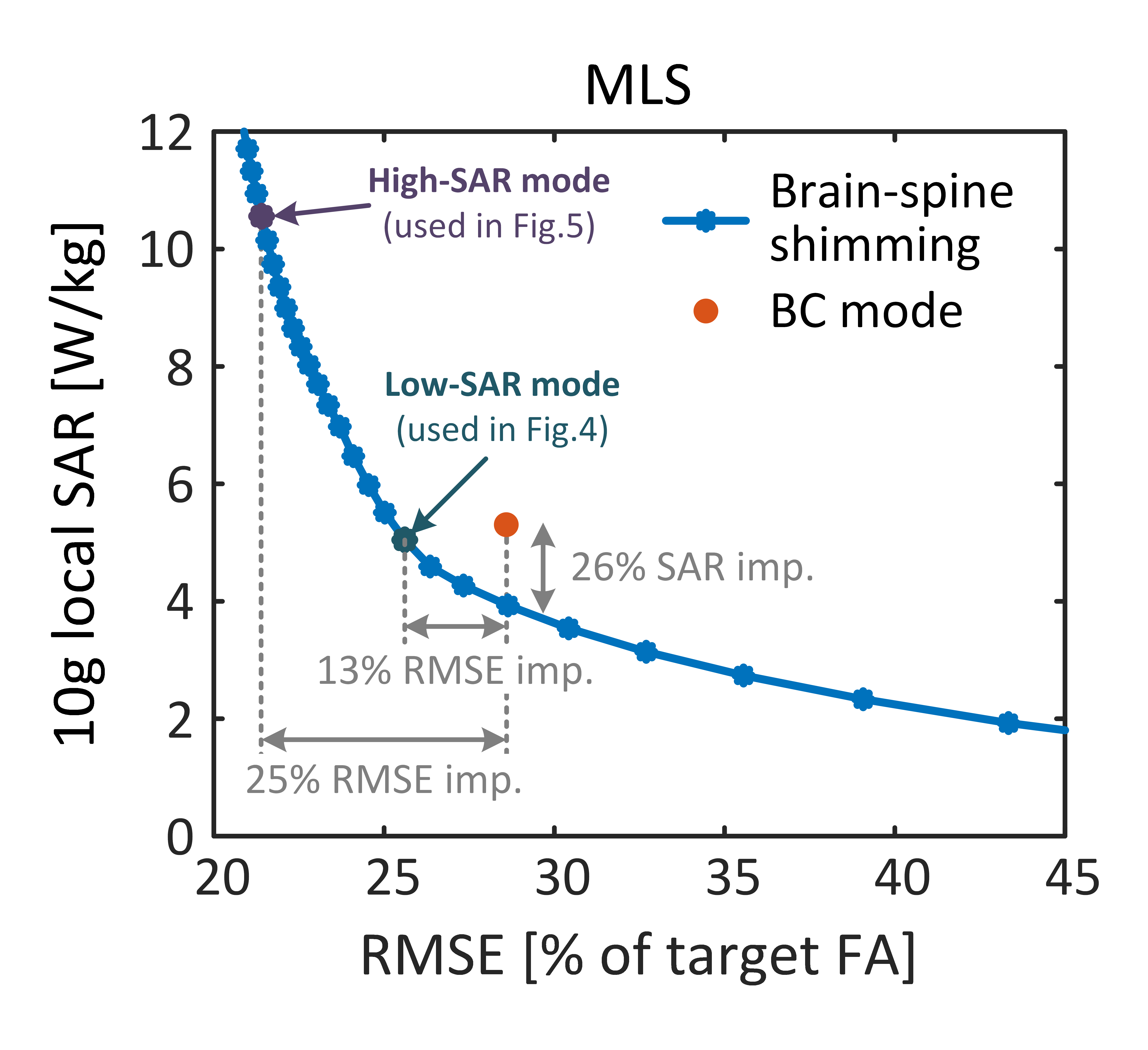
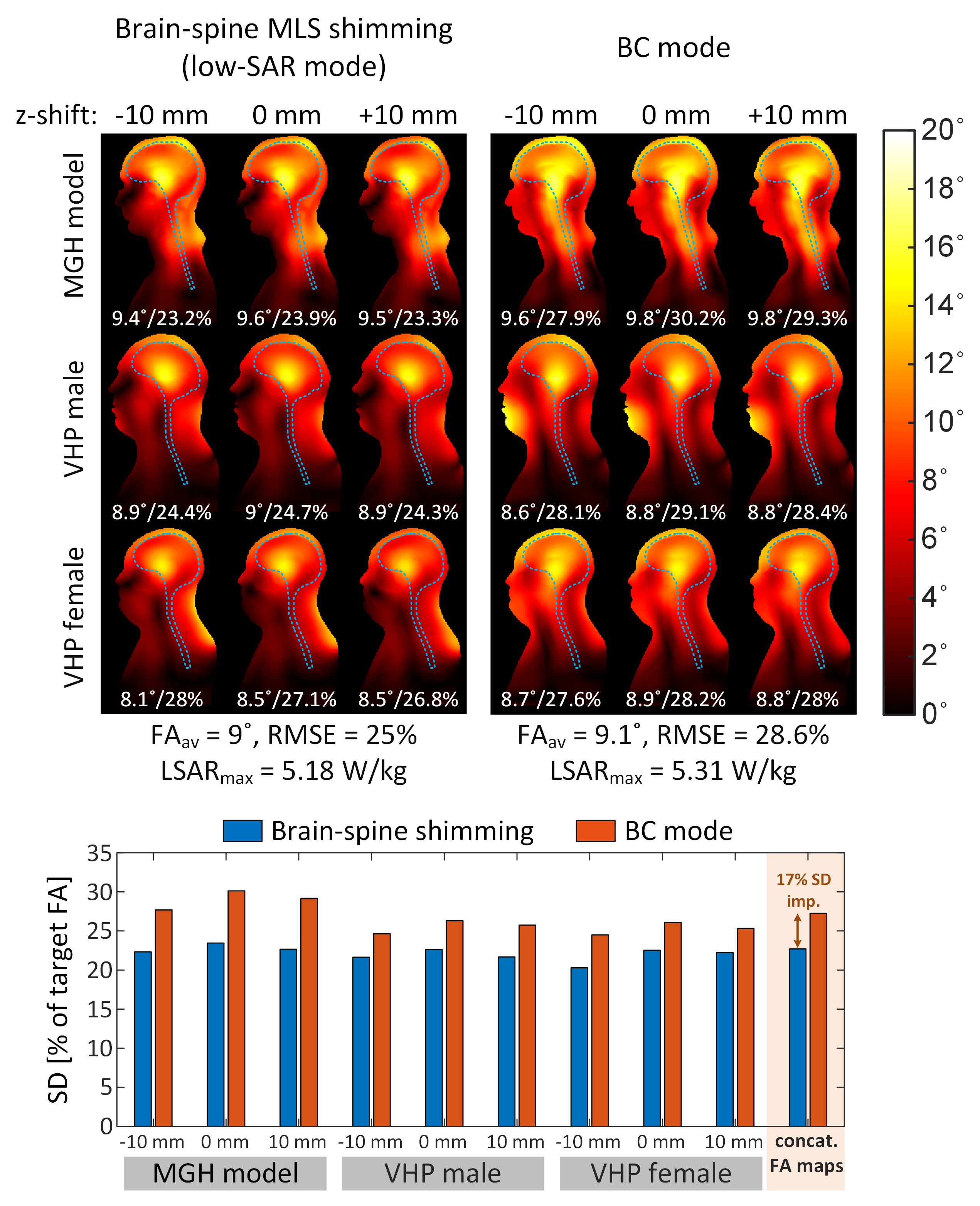
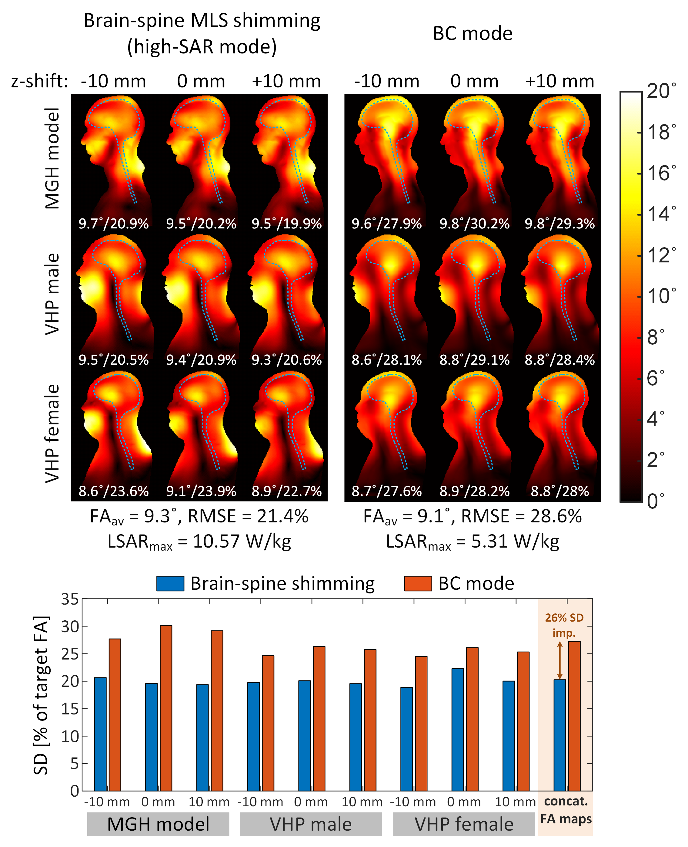
Figure 3 shows the MLS L-curve quantifying the tradeoff between flip-angle uniformity (flip-angle RMSE) and 10g local SAR from the multi-body models/positions VOPs. The “low SAR mode” MLS design yields a modest improvement in both RMSE at constant local SAR, and SAR at constant RMSE compared to the birdcage mode. However, if one is able to increase the local SAR by 2x compared to the birdcage mode, the “high SAR mode” solution yields a much more pronounced RMSE improvement (25%).Figure 4 displays sagittal flip-angle maps obtained with the BC mode and the low-SAR RF-shimming mode (Figure 5 shows the same thing, but for the high-SAR mode). These pulse solutions are the same as those shown in Figure 3. The high-SAR universal RF-shimming solution has 25% better RMSE and 32% better SD than the BC mode excitation, at the cost of 2x local SAR.
Conclusion and Discussion
Optimized pTx pulses are known to produce better RMSE vs local SAR tradeoffs than the birdcage mode6, but dramatically increase the complexity of the imaging workflow. Gras al.11 has introduced the concept of universal pulses in an effort to reduce pTx complexity to a level comparable to single channel mode operation (from the point-of-view of the operator). Here we show that universal MLS RF-shimming solutions create broadly useful RF excitations for head and neck imaging at 7T using a patient-friendly 16-channel pTx array. We propose two solutions that can be stored on the scanner and that the operator can easily toggle between: A low SAR solution, which leads to a modest 13% flip-angle uniformity improvement compared to the BC mode excitation, and a high-SAR excitation yielding a 25% RMSE improvement. Our excitations are universal in both B1+ and SAR, since our VOPs are also obtained by concatenation of multiple body models/positions, thus enabling true plug-and-play operation.Acknowledgements
No acknowledgement found.References
1. May MW, Hansen SJD, Mahmutovic M, et al. A patient-friendly 16-channel transmit/64-channel receive coil array for combined head-neck MRI at 7 Tesla. Magn Reson Med. 2022;88(3):1419-1433.
2. Massire A, Cloos MA, Luong M, et al. Thermal simulations in the human head for high field MRI using parallel transmission. J Magn Reson Imaging. 2012;35(6):1312-1321.
3. Makris N, Angelone L, Tulloch S, et al. MRI-based anatomical model of the human head for specific absorption rate mapping. Med Biol Eng Comput. 2008;46(12):1239-1251.
4. Noetscher GM. The CAD-Compatible VHP-Male Computational Phantom. In Makarov SN, Noetscher GM, Nummenmaa A, (Eds). Brain and Human Body Modeling 2020: Computational Human Models Presented at EMBC 2019 and the BRAIN Initiative(R) 2019 Meeting. Cham (CH) 2021:309-323.
5. Makarov SN, Noetscher GM, Yanamadala J, et al. Virtual Human Models for Electromagnetic Studies and Their Applications. IEEE Rev Biomed Eng. 2017;10:95-121.
6. Guerin B, Gebhardt M, Cauley S, et al. Local specific absorption rate (SAR), global SAR, transmitter power, and excitation accuracy trade-offs in low flip-angle parallel transmit pulse design. Magn Reson Med. 2014;71(4):1446-1457.
7. Eichfelder G, Gebhardt M. Local specific absorption rate control for parallel transmission by virtual observation points. Magn Reson Med. 2011;66(5):1468-1476.
8. Lee J, Gebhardt M, Wald LL, et al. Local SAR in parallel transmission pulse design. Magn Reson Med. 2012;67(6):1566-1578.
9. Grissom W, Yip CY, Zhang Z, et al. Spatial domain method for the design of RF pulses in multicoil parallel excitation. Magn Reson Med. 2006;56(3):620-629.
10. Brunner DO, Pruessmann KP. Optimal design of multiple-channel RF pulses under strict power and SAR constraints. Magn Reson Med. 2010;63(5):1280-1291.
11. Gras V, Vignaud A, Amadon A, et al. Universal pulses: A new concept for calibration-free parallel transmission. Magn Reson Med. 2017;77(2):635-643.
Figures