4405
Comparison of the transmit performance and Local SAR for multi-row parallel transmit coil arrays at 3 Tesla human brain MRI1Biomedical Engineering, King's College London, London, United Kingdom, 2Centre for the Developing Brain, King's College London, London, United Kingdom
Synopsis
Keywords: RF Arrays & Systems, Safety
MRI multi-row array coils can offer increased flexibility to control and tailor the RF field distribution through RF Shimming. The performance of various multi-row configurations of parallel-transmit (pTx) RF coil array for brain imaging at 3T is investigated using electromagnetic field simulations with digital human computational model for overlapping and non-overlapping loop coil elements in 16- to 24-channel single, double, triple-row arrays. We found that triple-row coil arrays improve the transmit field homogeneity in the entire volume of the head. The double-row coil array offers the best SAR efficiency among other investigated coils.Introduction
Parallel RF transmission (pTx) facilitates control of spatial variations in transmit fields which can increase signal homogeneity as well better managing RF power deposition in human tissue [1]. Multi-row coil arrays have been shown to have a better control of excessive tissue heating for electrically conductive implants at clinical field strengths [2] and to allow increased transmit efficiency and homogeneity, particularly along the longitudinal (head-foot) direction at ultra-high field [3]. Even at 3T, there is still significant transmit field inhomogeneity in the head when a birdcage is used for transmit. The aim of this work is to explore performance of parallel transmit coils with different row- and channel-number counts for achieving homogeneous RF transmit fields and assess SAR efficiency compared to the conventional head birdcage coil at 3T.Method
Six different pTx loop coil array configurations and a birdcage head coil were investigated using electromagnetic field simulations (FDTD, Sim4life 7.1(ZMT AG, Zurich Switzerland)) with a human phantom Duke [4] and a cylindrical magnet bore (length:1560mm, diameter:752mm, modelled PEC). A 3T head birdcage in circularly-polarised mode (lowpass, 16 legs)(Fig.1.a), 16ch-single-row non-overlapping (Fig.1.b), 16ch double-row non-overlapping (Fig.1.c), 16ch-double-row overlapping (Fig.1.e), 18ch-triple-row non-overlapping (Fig.1.d), 24ch triple-row overlapping (Fig.1.f) were designed on the same cylindrical former, (diameter:360mm, height:250mm), and placed head centred on the Duke model. In the double-row coils, the top row elements were rotated with respect to the bottom row and in the triple-row coils, the middle row elements were rotated with respect to the top and bottom row. For the overlapping coils (Fig.1.e,f), the loops are overlapped horizontally and vertically to increase the loop size and improve the decoupling. Care was taken to ensure that overlapped coils did not touch each other in the voxelised models. Multiport simulations(~90Mcells) with Gaussian excitation at 123 MHz were run using an Axware-GPU solver on a NVIDIA-RTX-A5000-card, and steady-state conditions of –25dB were achieved within hundred periods of simulation time. The resulting multiport impedance data was exported to co-simulation software (Optenni, Finland). The individual transmit (B1+ ) fields and electric fields (normalised at 1W power) are extracted on a head sensor volume 201×251×231mm, resampled to 1mm isotropic image grid and exported to Matlab(MatWorks, Inc.). Q-matrices are derived from simulated E-fields and 1-g tissue mass-average to evaluate SAR1g avg [5]. RF shimming was performed for each coil design with a uniform target field using Magnitude Least Square (MLS) Optimisation regularised by total input power [6,7]. By varying the Tikhonov regularisation parameter (from 0.1 – 15) [5], L-curves that demonstrate the trade-off between excitation error and power requirement were obtained and used to select an optimal shim that corresponds to the lowest cost function value (Fig.2). After RF shimming, coil performance was assessed by constructing histograms of B1+ values, looking at maximum intensity projections of B1+ and of local SAR, and estimating SAR efficiency (B1+/√ SARmax,1g avg).Results
For the tuned coils, maximum reflection coefficients are: -18dB for birdcage, -21dB for non-overlapping coils and -16dB for overlapping coils (Fig.1), while the maximum coupling coefficients are: -18dB for birdcage and varies between -8 and -5dB for pTx coils. Optimal regularisation parameter values for each coil array were determined from the L-curves (black dots in Fig.2), the corresponding optimal shim weights recorded. The L-curve of triple-row coils is closer to the x-axis compared to other coils which results in the best transmit field homogeneity/power trade off. The triple-row non-overlapping coil can achieve the smallest homogeneity error, but at a higher power requirement. The overlapping coils appear to provide the most stable error versus power configurations. The single-row coil cannot achieve high homogeneity but can achieve it best performance at lower power than all other coils, except the overlapping triple-row coil. The triple-row non-overlapping and overlapping coils provide the most homogenous transmit field (Fig.3.d,f) with the lowest coefficient of variations (COV)(7% and 8%,respectively) which have ~30% less RF variation than double-row coils (Fig.3.c,e) and are nearly 2 times more homogenous than single-row and birdcage coil (Fig.3.a,b). This is illustrated in figure Fig.3(Fig.3.a-f.c), where the distribution of the transmit fields becomes narrower as the complexity of the coils increases. The SARmax,1g avg values showed that single-row(0.03W/kg/W) (Fig.4.b) is 2 times lower than the double-row non-overlapping (0.03W/kg/W)(Fig4.b) and triple-row non-overlapping (0.03W/kg/W)(Fig.4.c) coils and 2.5 times less than double-row overlapping (Fig.4.e) and triple-row overlapping(Fig3.f) coils. The highest SAR efficiency is obtained by the double-row overlapping (0.85μT/√(W/kg)), which is around 15% more than single-row, double-row non-overlapping and birdcage coils and around 30% more efficient than triple-row coils.Discussion and Conclusion
The results show that increasing the number of rows of pTx coil improves the transmit field’s homogeneity, as triple-row coils provided the lowest coefficient of variations in the entire volume of the head. The triple-row non-overlapping coil can achieve the most homogeneous RF fields, while the triple-row overlapping coil has the best balance between RF homogeneity and the required power. The double-row non-overlapping coil provides the highest SAR efficiency solution among the coils. In addition to improving homogeneity in regular MRI, there is potential for pTx to help reduce focal hotspots when there are implants such as deep brain stimulation electrodes, and this will be a subject of future study.Acknowledgements
This work was supported by EPSRC DTP, by core funding from the Wellcome/EPSRC Centre for Medical Engineering [WT203148/Z/16/Z] and by the National Institute for Health Research (NIHR) Biomedical Research Centre based at Guy’s and St Thomas’ NHS Foundation Trust and King’s College London and/or the NIHR Clinical Research Facility. The views expressed are those of the author(s) and not necessarily those of the NHS, the NIHR or the Department of Health and Social Care. Authors thank to Dr. Shaihan Malik the code MLS Optimisation.References
[1] Zhu, Y. (2004). Parallel excitation with an array of transmit coils. Magnetic resonance in medicine. 51(4), 775–784. https://doi.org/10.1002/mrm.20011
[2] Guérin, B., Angelone, L.M., Dougherty, D.D., & Wald, L.L. (2019). Parallel transmission to reduce absorbed power around deep brain stimulation devices in MRI: Impact of number and arrangement of transmit channels. Magnetic Resonance in Medicine, 83, 299 - 311.
[3] Kozlov, M., Bode, J., Bazin, P., Weiskopf, N., Möller, H.E., & Shajan, G. (2017). Comparison of 7T 16-channel dual-row transmit arrays. 2017 International Conference on Electromagnetics in Advanced Applications (ICEAA), 1264-1267.
[4] Gosselin, M. C., Neufeld, E., Moser, H. Development of a new generation of high-resolution anatomical models for medical device evaluation: the Virtual Population 3.0. Physics in medicine and biology, 59(18), 5287–5303. https://doi.org/10.1088/0031-9155/59/18/5287
[5] Ipek, Ö., Raaijmakers, A.J., Lagendijk, J.J., Luijten, P.R., & Berg, C.A. (2014). Intersubject local SAR variation for 7T prostate MR imaging with an eight‐channel single‐side adapted dipole antenna array. Magnetic Resonance in Medicine, 71.
[6] Setsompop, K., Wald, L. L., Alagappan, V., Gagoski, B. A., & Adalsteinsson, E. (2008). Magnitude least squares optimization for parallel radio frequency excitation design demonstrated at 7 Tesla with eight channels. Magnetic resonance in medicine, 59(4), 908–915. https://doi.org/10.1002/mrm.21513
[7] https://gitlab.com/bioengmri/ptx
Figures
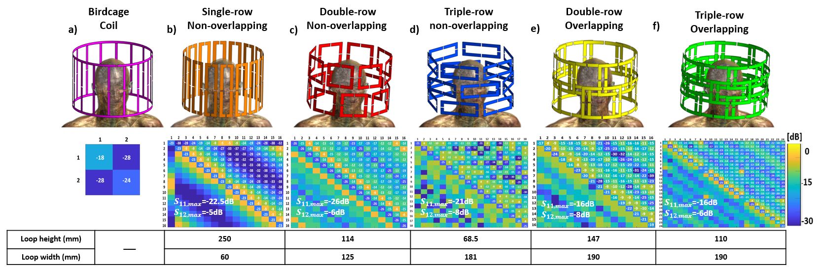
Fig. 1. RF Coil Designs of a) birdcage b) 16ch single-row non-overlapping c) 16ch double-row non-overlapping d) 18ch triple-row non-overlapping, e) 16ch double-row overlapping f) 24ch triple-row overlapping parallel-transmit array for human head, their simulated respective S-matrices and the height and width of the loops of each coils. All pTx coils and birdcage covers the same height and at similar diameter.
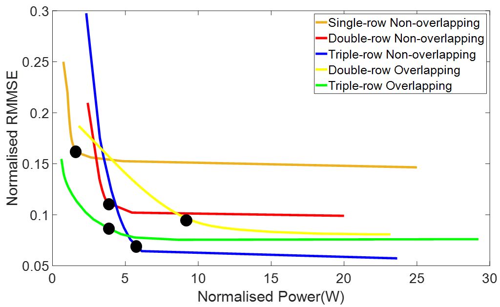
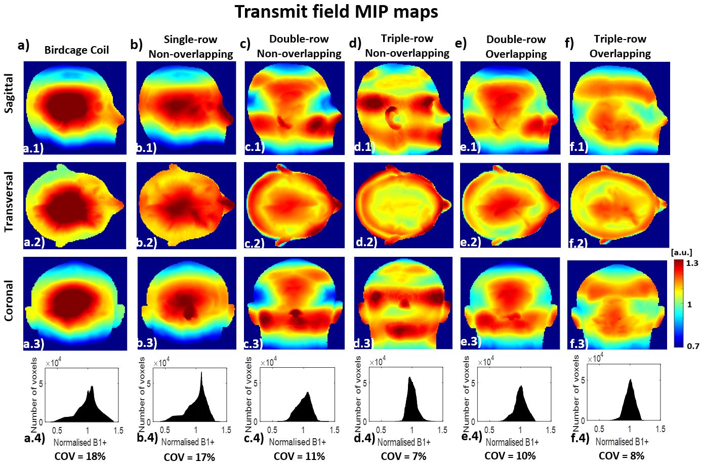
Fig. 3. B1+ maximum intensity projection (MIP) in the sagittal, transversal and coronal plane for the birdcage (a.1-3), 16ch single-row non-overlapping (b.1-3), 16ch double-row non-overlapping (c.1-3) ,18ch triple-row non-overlapping (d.1-3), 16ch double-row overlapping (e.1-3) and, 24ch triple-row overlapping coils (f.1-3), normalised to mean B1+. The histograms of the distribution of the normalised transmit fields (a-f.4), Coefficient of variation values ((s(| B1+ |)/μ(| B1+|))) of each coil under the distribution.
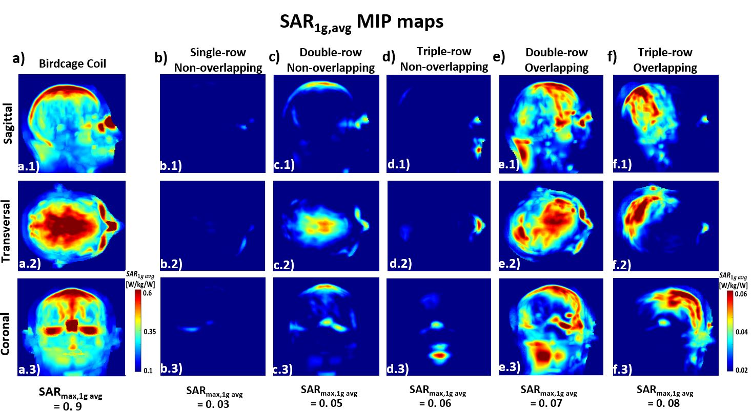
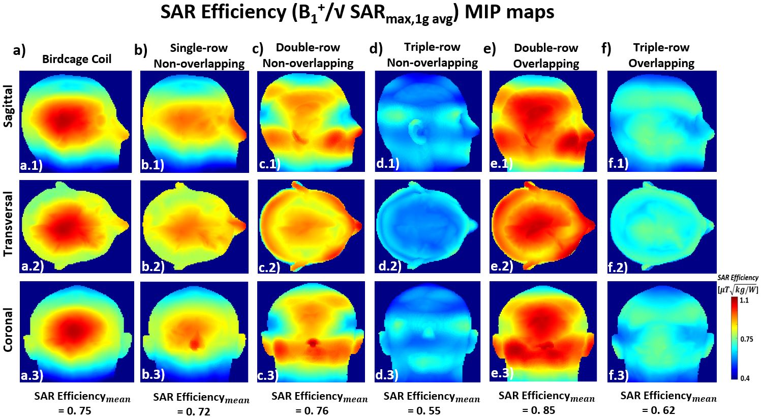
Fig.5. SAR efficiency (B1+/√ SARmax,1g avg) maximum intensity projection (MIP) in the sagittal, transversal and coronal plane the birdcage (a), 16ch single-row non-overlapping (b), 16ch double-row non-overlapping (c), 18ch triple-row non-overlapping (d), 16ch double-row overlapping (e) and, 24ch triple-row overlapping coils (f), input power normalised to 1W total input power.