4398
3D Printed Alignment Apparatus for Retrofitted Rodent PET-MRI at 9.4 Tesla1Buffalo Neuroimaging Analysis Center, Department of Neurology at the Jacobs School of Medicine and Biomedical Sciences, University at Buffalo, The State University of New York, Buffalo, NY, United States, 2Center for Biomedical Imaging, Clinical and Translational Science Institute, University at Buffalo, The State University of New York, Buffalo, NY, United States
Synopsis
Keywords: PET/MR, Preclinical
We developed a retrofitted alignment apparatus that attaches to the MRI’s motor-driven automated positioning system and enables simultaneous preclinical PET/MRI at 9.4T with a stand-alone microPET ring. The system leverages 3D printing technology to achieve stable alignment between the two modalities, consistent placement of animals, and rapid reconfiguration between PET-MRI and MRI-only experiments. Thereby addressing the shortcomings of other retrofitted designs and proving simultaneous PET-MRI capabilities at a reduced cost.Introduction
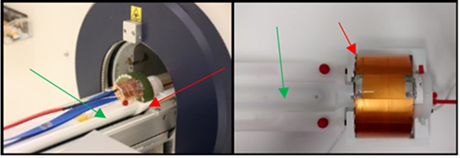
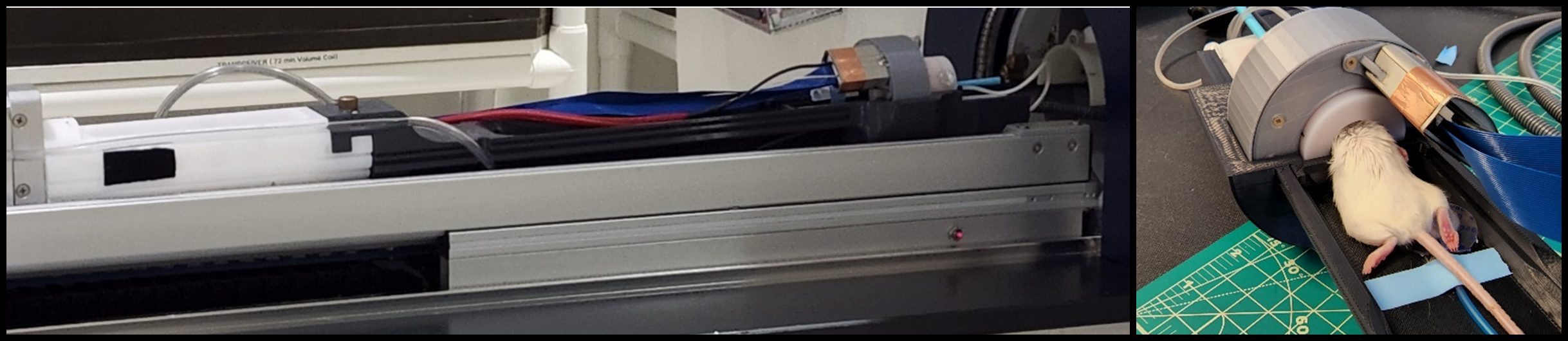
Simultaneous PET and MRI with a retrofitted microPET ring has been demonstrated recently at 9.4 Tesla1-4. These studies employed a simple multi-component alignment apparatus prototype3 to attach the PET ring to the MRI's animal positioning system and hold it inside the magnet (Fig .1). Initial experience with the prototype2,3 revealed several shortcomings of the original design: (i) the mechanical connectors did not provide sufficient stability to hold the apparatus stationary due to the heavy weight of the equipment, resulting in x-y-position drifting; (ii) the z-location was determined through laser-calibrating the MRI’s positioning system, but the reproducibility of the z-positioning was low (mm-range); (iii) the design involved moving both the RF coil and the PET ring out of the way for animal positioning, resulting in high wear and tear and further limiting the z-position accuracy; (iv) the embedded water heating system did not reach close enough to the PET ring for efficient heat transfer. The present work introduces an improved design that overcomes the identified limitations of the original holding apparatus and brings us one step closer to retrofitting preclinical MRI scanners with PET capabilities5.Methods
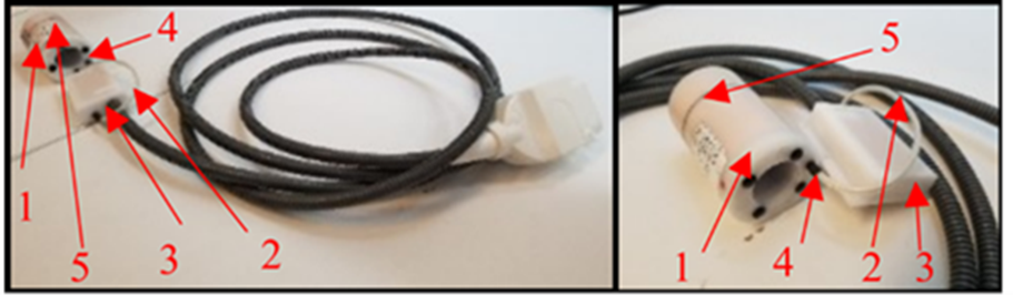
We designed the apparatus to be attached to the motor-driven automated positioning system (Bruker AutoPac) of a 20 cm horizontal-bore 9.4T magnet (Bruker Biospin 94/20USR) equipped with a gradient coil with 114 mm inner diameter (Bruker BGA-12S HP). PET capabilities were provided by a shielded microPET ring with 44/80 mm inner/outer diameters and 25mm depth (SynchroPET Inc., Stony Brook, NY; LYSO 18.5x9.6x6 mm3, 4x8 pixels; APD)6. Several design criteria were identified for the holding apparatus: (i) must hold a 1H quadrature transceiver coil (Bruker T12969V3; 23/44 mm inner/outer diameters) with filter box (Fig. 2), isoflurane anesthesia gas outlet, and vitals monitoring equipment (temperature probe, respiration pillow; ERT Model 1030, SA Instruments, Inc.); (ii) consistent and stable (axial and angle) placement of the PET ring and volume coil for accurate system attenuation map reconstruction; (iii) rigid attachment to the automated positioning system for smooth workflow; (iv) the system and animal can be set up outside the bore; (v) fine adjustment of x-y-z positioning relative to positioning system; (vi) positioning of animals without the need to remove the PET ring or RF coil; (vii) grooves to hold wires, tubes and cables stationary; (viii) adequate warm-water heating of animal; (ix) flat animal cradle that is easy to disinfect; (x) MRI-compatible materials; (xi) no deformation due to mechanical stress. We designed the apparatus in Autodesk Inventor (Autodesk; Professional 2022) and 3D printed components using acrylonitrile butadiene styrene (ABS; Xometry, MD, USA).Results
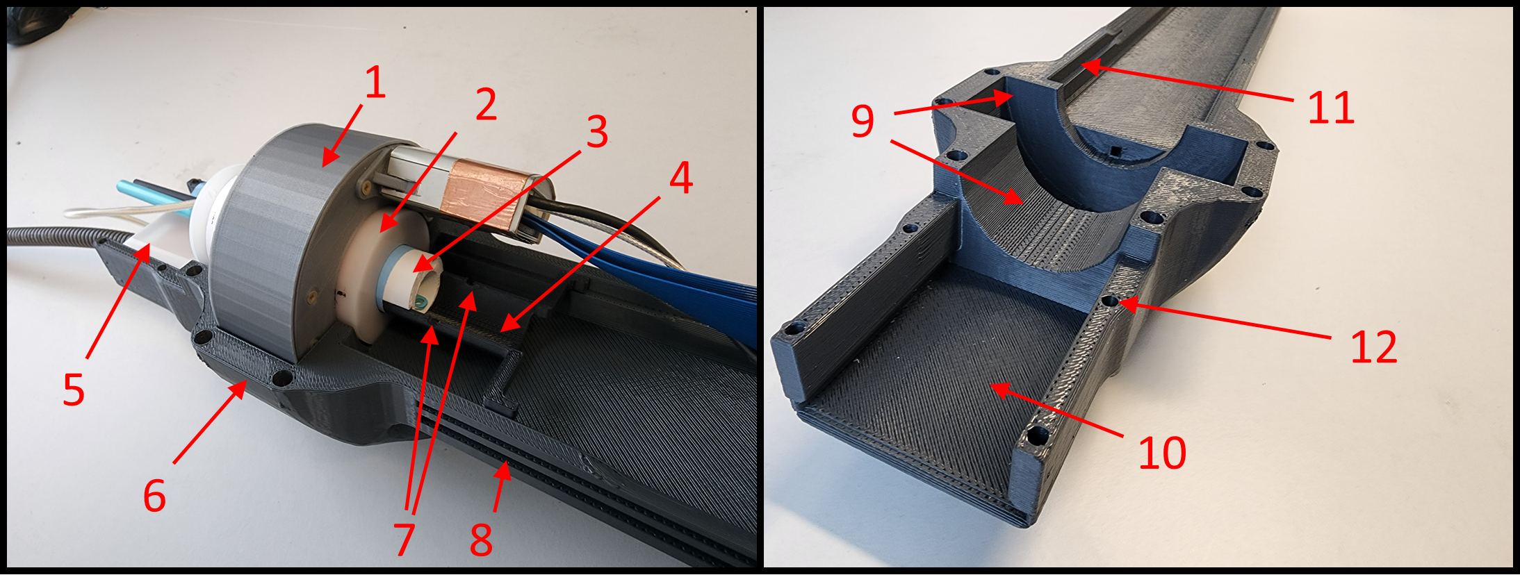
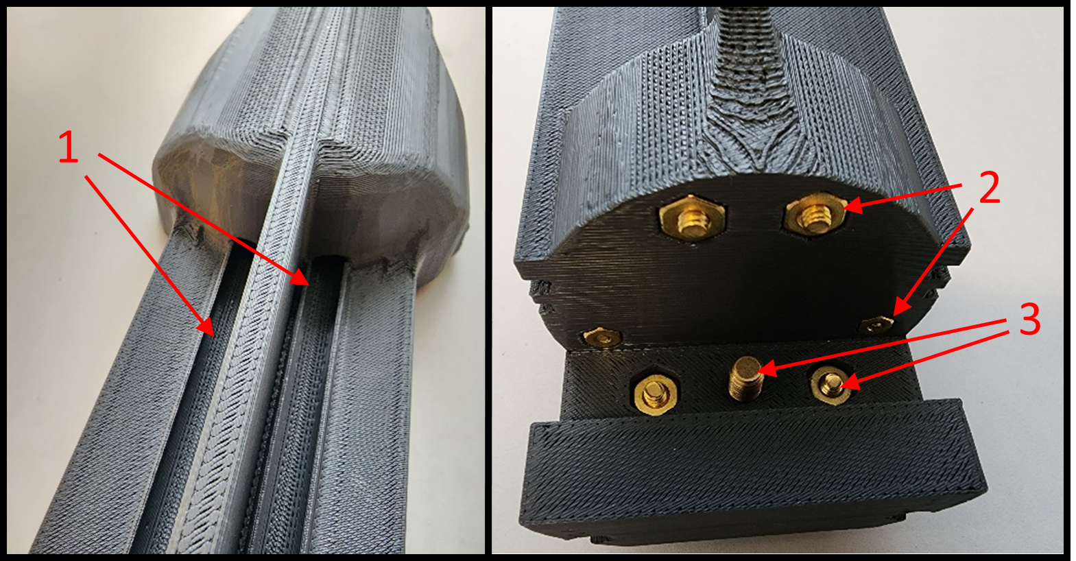
Figures 3-5 provide an overview of the designed apparatus. The apparatus was designed as a single piece (Fig. 3.6) that replaced the original prototype holder as well as the originally used stock cradle (Fig. 1, green arrow). The design criteria were met by implementing the following features: (i) Static molds for the volume coil and PET ring ensured fixed x, y, and z locations for consistent placement (Fig. 3.1-3.2, 3.9). (ii) Integrated space for the filter box close to the coil for length-compressed design (Fig. 3.5). (iii) side grooves for attaching the wires, tubes, and cables (Fig. 3.8). (iv) Anesthesia system track with the anesthesia nose cone on the nose cone track (Fig 3.3-3.4, 3.11). Embedded tracks for heated water tubes that reach close to RF coil (Fig. 4.1). The attachment of the new system to the MRI’s positioning system (Fig. 5) utilized a similar attachment mechanism as the product animal cradle with a brass nut and bolt system (Fig 4.2-4.3) to enable stable attachment and easy removal to the ERT module (white). Figure 3 shows the front section of the system fully assembled with the anesthesia nose cone on the nose cone track slid out of the volume coil. The nose cone track rests on the anesthesia system track and prevents the nose cone from rotating during imaging. The nose cone track possesses nocks that can be imaged though a ZTE scan to orientate the MRI scan to the PET ring (Fig. 3.7). The system enables setting up the animal outside of the RF coil and PET-ring assembly on the open space of the cradle. The animal is then slid into the volume coil with the imaging region centered with respect to both modalities.Discussion
The presented retrofitted alignment apparatus addresses the weakness of the previously presented design to enable reproducible preclinical PET-MRI at 9.4T. Reliance on 3D printing technology enabled rapid adjustment of the setup to site-specific needs to facilitate a widespread adoption of preclinical PET-MRI at ultra-high field strength.Conclusion
The proposed apparatus enables retrofitted PET-MRI in preclinical MRI systems. Future research will systematically assess the reproducibility and accuracy of data collection and geometric orientation of the design, as well as the impact of different 3D printing materials on the mechanical stability in a high-throughput environment. The use of 3D printing technology in the development process will enable a rapid improvement of the design when shortcomings are identified. We intend to make the final CAD design publicly available to enable adaption of the retrofitted holding attachment for other MRI systems, facilitating a wider availability of retrofitted PET-MRI.Acknowledgements
Research reported in this publication was supported by a research collaboration agreement with SynchroPET Inc., Stonybrook, NY, USA and by the National Center for Advancing Translational Sciences of the National Institutes of Health under Award Number UL1TR001412. The content is solely the responsibility of the authors and does not necessarily represent the official views of SynchroPET, Inc or the National Institutes of Health.References
1. P. Choudhary et al., "Longitudinal [18F]FDG PET-MRI at 9.4 Tesla in Twitcher mice using spatial normalization " presented at the PSMR, 2018.
2. P. Choudhary et al., "Longitudinal Multi-modal Multi-parametric Imaging of the Twitcher mouse model of Krabbe Disease," presented at the PSMR, 2019.
3. Y. Sinelnikov, N. Bertolino, and F. Schweser, "Small Animal PET Scanner for PET-MRI at Ultra-High Magnetic Fields " presented at the PSMR, 2016.
4. F. Schweser et al., "Truly simultaneous preclinical PET-MRI in a 20cm 9.4 Tesla magnet with a retrofitted miniature detector: Initial results in the twitcher mouse model of Krabbe disease," 2018.
5. F. Nensa, K. Beiderwellen, P. Heusch, and A. Wetter, "Clinical applications of PET/MRI: current status and future perspectives," (in eng), Diagn Interv Radiol, vol. 20, no. 5, pp. 438-447, Sep-Oct 2014.
6. S. H. Maramraju et al., "Small animal simultaneous PET/MRI: initial experiences in a 9.4 T microMRI," (in eng), Physics in medicine and biology, vol. 56, no. 8, pp. 2459-80, Apr 21, 2011.
Figures