4394
Implementation of Proposed Methods for MR-Guided Transperineal Prostate Interventions: Real Time Trajectory Calculation and Monitoring1Medical Physics, University of Wisconsin - Madison, Madison, WI, United States, 2Radiology, Mayo Clinic, Rochester, MN, United States, 3Radiology, University of Wisconsin - Madison, Madison, WI, United States, 4Biomedical Engineering, University of Wisconsin - Madison, Madison, WI, United States
Synopsis
Keywords: Interventional Devices, Visualization
Utilizing MR guidance for minimally-invasive prostate interventions is known to improve the precision and accuracy of the procedure. Previous work has been done to develop and propose an integrated platform for conveniently providing this image guidance to clinicians for use with transperineal prostate interventions. Since then, the proposed methodology has been applied, in a limited capacity, to assist in an in-vivo prostate biopsy. It was found that the trajectory computation component of the platform was able to accurately guide needle placement to the clinician-selected anatomical regions with little need for correction.Introduction
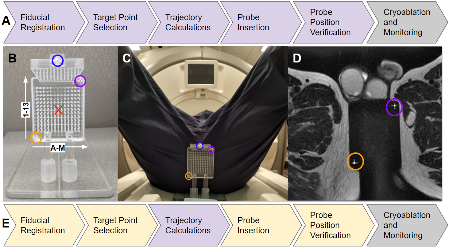
During minimally-invasive interventions of the prostate, intermittent or real-time MR-guidance is effective in helping clinicians achieve effective probe placement through roadmap imaging and post-insertion validation1. We have been working towards meeting needs for image guidance tools, particularly for in-bore, real-time, transperineal approaches1, that require accounting for multiple needle paths in the same procedure. We have worked to develop a platform compatible with multiple scanner manufacturers (RtHawk, Menlo Park CA) for guiding the placement of, and monitoring, cryoprobes and biopsy devices during transperineal minimally–invasive prostate interventions, as outlined in Figure 1A2. We now investigate the efficacy of the proposed methodology on our first patient.Methods
This work is completed under IRB approval here the patient consented to use of a limited portion of the trajectory guide alignment software intraprocedurally to verify physician-selected grid holes on the prostate trajectory guide. Specifically, the fiducial registration, target point selection, and trajectory calculations (Figure 1E) were tested through a separate computer based on outputs from the scanner-native sequences and interfaceFiducial Registration:
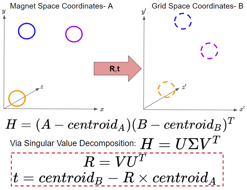
Placing an external guidance grid adjacent to the patient’s perineum (Fig. 1C), a single scan covering the extent of the prostate and the 3 fiducials on the trajectory guide (colored circles in Fig. 1C) is acquired. In this way, the prostate and the fiducials (Fig. 1D) are visible on the same scan. From here, the spatial coordinates of the fiducials, relative to the bore’s isocenter, can be determined using annotation tools built into the scanner interface. These coordinates can then be relayed to the guidance platform, where prior-known measurements of the grid’s inter-fiducial spacings are used to coregister the grid to a scanner-bore-orthogonal space, as outlined in Figure 2.
Targeting and Trajectory:
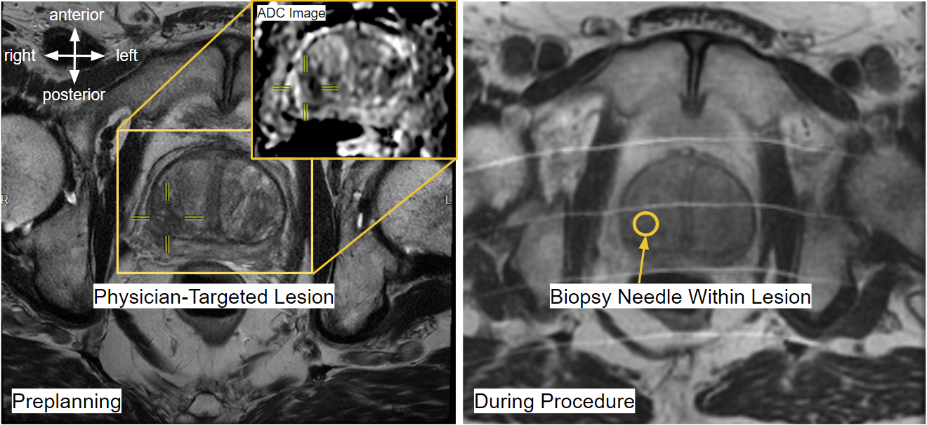
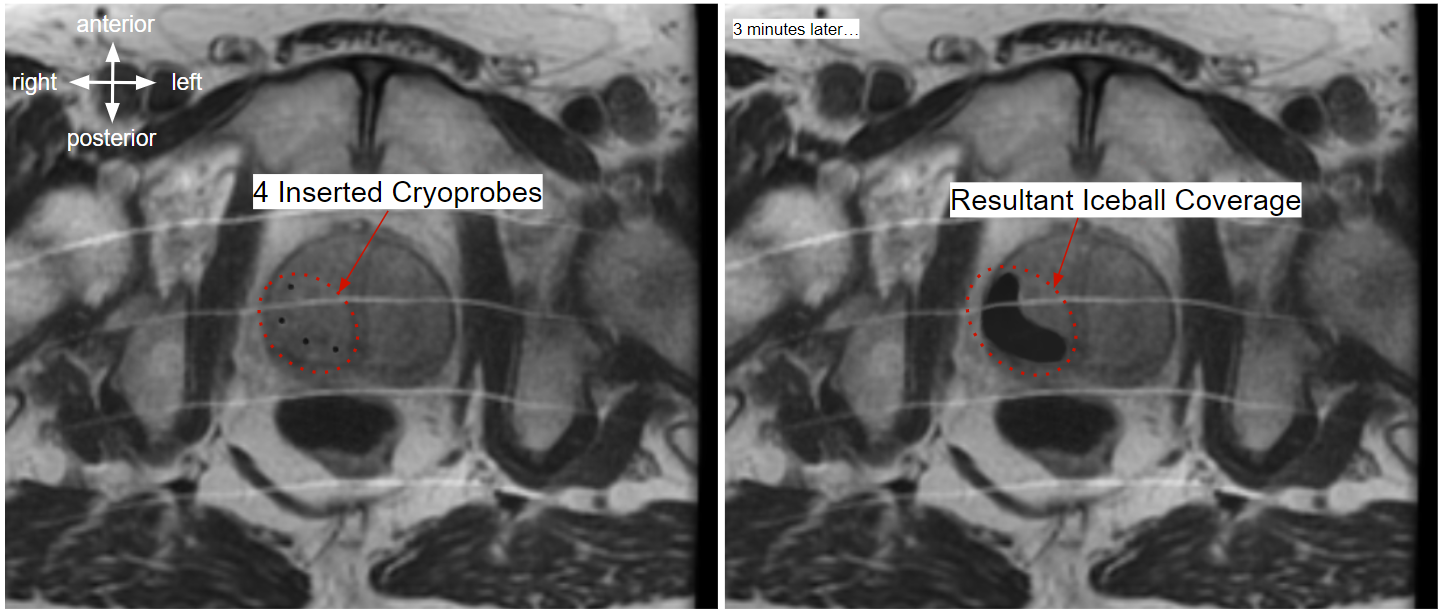
Knowing rotation and translation matrices, R and t, between the scanner’s frame of reference (Magnet Space) and the grid’s frame of reference (Grid Space), we can select any number of target points on the prostate (identified using a clinician’s expertise) in magnet space, transform them into grid space, backproject onto the face of the grid, and bin into the optimal grid hole. In this way, we can go from targeted points on a prostate lesion to best estimates of trajectory origins. To verify needle placement, additional scans are acquired after insertion. In this work, all images were acquired on a 1.5T GE machine. Needles are visible in these MR scans, as shown in Figure 3. Any needles that do not follow their intended trajectories may be re-inserted and then re-verified with another scan. When the clinician is satisfied with the needle positioning, biopsies samples may be collected, or cryoablation induced, depending on the procedure. Proper probe placement is a matter of physician judgment. In cryoablations, ice expands around the tip of the probe, and the surgeon must target such that the expansion zone covers the lesions without impinging on sensitive organs like the ureter or rectum. An example of needle placement and corresponding ice coverage is shown in Figure 4.
In Vitro Needle Deflection:
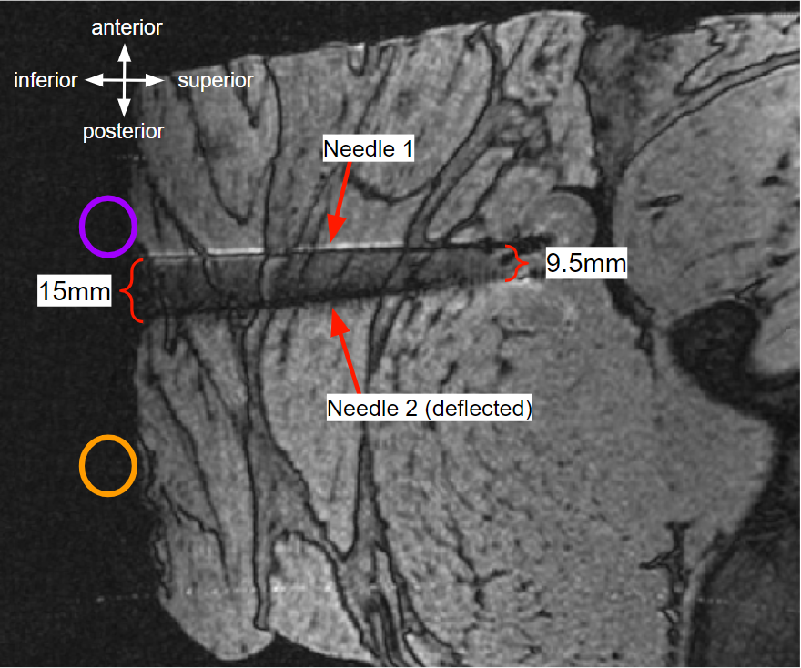
Needle deflection during needle insertion is a recognized phenomena in some types of image-guided surgery interfaces3. Our previous work had validated the process using gelatin phantoms2. To emulate living tissue, we inserted cryoprobes into a meat-based phantom and then imaged the needle signal void using MRI.
Results
In the ex-vivo meat-based phantom, we found that needles sometimes deflected off intended trajectories. Deflection occurs at tissue interfaces, like the muscle fascia in this phantom or targeted prostate lesions, which can be more rigid in some patients. Among the 10 needles placed in our first in-vivo case, 4 (40%) of the needles required readjustment from the initial grid hole informed by the trajectory calculation methodology, although deflection of the needle within pelvis tissues caused poor tracking in the majority of the repositionings reported here.Discussion
Using the designed methodology, we were able to demonstrate our trajectory guide alignment on a patient biopsy procedure with then ten needle placements.Our successful demonstration of alignment of the trajectory guide will be used to secure an IRB for validation of the entire real-time, integrated workstation for probe alignment, insertion, validation, and monitoring.
The needle deflection effects, noted in Figure 5, highlight the value of real-time imaging during needle insertion and placement validation prior to biopsy or cryoablation. With appropriate guidance, an interventionist can detect and correct for deflection as it occurs, rather than only discovering it on a post-insertion verification scan.
Conclusion
The proposed methodology was able to guide an interventionist through the process of fiducial registration, target selection, trajectory calculation, probe insertion, and position verification for 10 biopsy needles in a human patient. Future work will study the value of simplifying the procedural workflow by abstracting away the complexity of prescribing multiple scan planes that track and validate multiple needle insertions. Using our integrated platform, which is compatible with multiple manufacturer systems through use of the RtHawk communication protocol and its human interface, we will also test real-time cryoablation monitoring with upcoming scheduled cases.Acknowledgements
This work was completed with funding from the University of Wisconsin School of Medicine and Public Health and the UW Department of Radiology.
We thank the Mayo Clinic Interventional MRI Program and Mayo Clinic Department of Engineering for their collaboration on this project.
We acknowledge GE Healthcare for research support.
References
[1] Woodrum DA, Gorny KR, Mynderse LA. MR-Guided Prostate Interventions. Top Magn Reson Imaging. 2018 Jun;27(3):141-151. doi: 10.1097/RMR.0000000000000155. PMID: 29870466.
[2] Lilieholm T, Moskwa R, Ozhinsky E, Woodrum D, Block WF, Knavel Koepsel E, Platform for Real-Time Multiplane Targeting and Monitoring of Minimally-Invasive Image-Guided Prostate Cryoablation Procedures, Proc. of International Society of Magnetic Resonance in Medicine, 2022.
[3] Abolhassani N, Patel RV. Deflection of a flexible needle during insertion into soft tissue. Conf Proc IEEE Eng Med Biol Soc. 2006;2006:3858-61. doi: 10.1109/IEMBS.2006.259519. PMID: 17946584.
[4] K. S. Arun, T. S. Huang and S. D. Blostein, "Least-Squares Fitting of Two 3-D Point Sets," in IEEE Transactions on Pattern Analysis and Machine Intelligence, vol. PAMI-9, no. 5, pp. 698-700, Sept. 1987, doi: 10.1109/TPAMI.1987.4767965.
Figures