4386
Simulation of the Electric Transfer Function of Partially Inserted Guidewires1University of California Davis, Sacramento, CA, United States, 2School of Biomedical Engineering and Imaging Sciences, King's College London, London, United Kingdom, 3Centre for the Developing Brain, King's College London, London, United Kingdom, 4Davis Senior High School, Davis, CA, United States
Synopsis
Keywords: Interventional Devices, Safety
Endovascular interventional devices can heat when used in an MRI system. The heating mechanism can be evaluated using the electric transfer function. In this work we evaluated the TF for a partially inserted guidewire as used in practice, at frequencies corresponding to 0.55T, 1.5T, and 3T. The study revealed that the transfer function varies dramatically with insertion depth for some frequencies and not others.Introduction
Catheter interventions are performed to treat cardiac conditions and in treating some cancers1, however, the use of endovascular interventional devices is limited due to heating caused by coupling of the device to the MR scanner’s RF coils. The method of determining the electric transfer function (TF) has been used to model the mechanism of heating at the tip of a wire from incident RF energy2. Previous work has shown that the TF model can predict heating at the tip of a wire fully immersed in a dielectric material. However, in practice guidewires are partially inserted to allow the operator to maneuver them externally. Although the effect of wire length on tip heating has been investigated3, the case of a partially inserted wire has not been modeled. In this work we investigate the behavior of a partially inserted wire using the TF method.Methods
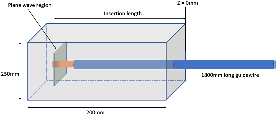
The transfer function of a 180cm long wire in a dielectric medium (permittivity =78, conductivity = 0.47 Sm-1) was calculated from simulation (Sim4Life, ZMT, Zurich, Switzerland). A wire was excited at the tip with RF energy produced by counter propagating plane waves to get a pure electric field4. The law of reciprocity5 was invoked so that the resulting current distribution along the wire is the TF.The guidewire was modeled as an insulated 1mm diameter wire with 10mm of the tip exposed by removing the insulation to create a worst-case condition. The wire was partially inserted into a rectangular phantom measuring 250mmx250mmx1200mm filled with dielectric medium (figure 1). The insertion depth was increased by moving the phantom at 50mm intervals, away from the wire, from its initial position of 100mm from the phantom wall.
The TF was modeled for insertion depths ranging 100mm-1100mm at 50mm intervals. At each insertion depth the TF was simulated for the frequencies 23MHz, 64MHz, and 128MHz, corresponding to 0.55T, 1.5T, and 3T, respectively. The TFs for each case were compared in magnitude and phase.
Results
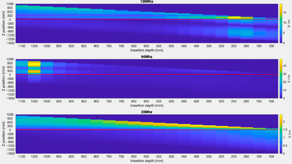
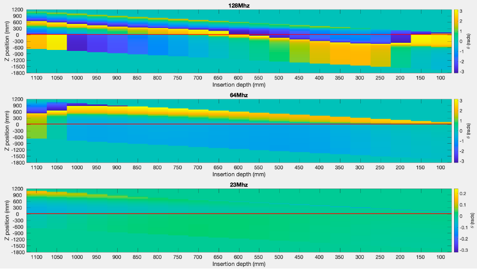
The TF magnitude profiles are plotted in figure 2 for all insertion depths and frequencies. The TF profile changes significantly with insertion depth and the change is most extreme at 64MHz. The peak TF values and corresponding insertion depth were 19.2 m-1 at 250mm, 48.0 m-1 at 1050mm, and 2.4 m-1 at 450mm, for frequency 128MHz, 64MHz, and 23MHz respectively. The phase of the TF is plotted in figure 3 for each frequency.Discussion
The TF of a partially inserted wire changes drastically with inserted depth, as expected from experiments varying the wire lengths. Experimental results from Armenean et. al. show similar resonant behavior. In this study we evaluated the effect of frequency on the TF, demonstrating that the TF can identify the field strength/frequency that least causes tip heating for a given wire length. In this work, evaluating a 1800mm long guidewire, we observed two related effects: (i) the ‘shape’ of the TF varies with insertion depth at all frequencies, and this effect is strongest at 64MHz; (ii) the overall peak amplitude of the TF also varies with frequency and is also observed to be strongest at 64MHz. This is in agreement with experimental results from Konings et. al. of a partially immersed guidewire6.Strong phase variation of the TF is observed at the higher frequencies; this can actually lead to reduced total scattered E-fields at the tip since contributions from incident fields at different portions of the wire cancel each other out. On the other hand, phase and amplitude variation are very smooth for the 23MHz frequency, which may be expected since the wavelength is largest at this frequency.
It is commonly assumed that higher frequencies pose the largest risk, though this work found strongest scattered fields at 64MHz. We also found that the properties of a guidewire will depend critically on the insertion depth, and that the TF is generally much higher inside the dielectric than outside. This latter observation could mean that electric fields incident on the external portion of a wire do not generally cause high fields at the tip.
Conclusion
We have compared the TF for a range of insertion depths and frequencies and found that the TF method can be used to predict the behavior of a partially inserted wire, as used in an interventional setting.Acknowledgements
This work was supported by core funding from the NCI Comprehensive Cancer Center at the University of California Davis [5K12CA138464-12] and Wellcome/EPSRC Centre for Medical Engineering [WT203148/Z/16/Z] and by the National Institute for Health Research (NIHR) Biomedical Research Centre based at Guy’s and St Thomas’ NHS Foundation Trust and King’s College London and/or the NIHR Clinical Research Facility. The views expressed are those of the author(s) and not necessarily those of the NHS, the NIHR or the Department of Health and Social Care.References
1. Srinivasan, V. M. et al. Advances in endovascular neuro-oncology: Endovascular selective intra-arterial (ESIA) infusion of targeted biologic therapy for brain tumors. Journal of NeuroInterventional Surgery vol. 12 197–203 (2020).
2. Park, S. M., Kamondetdacha, R. & Nyenhuis, J. A. Calculation of MRI-induced heating of an implanted medical lead wire with an electric field transfer function. Journal of Magnetic Resonance Imaging 26, 1278–1285 (2007).
3. Armenean, C. et al. RF-induced temperature elevation along metallic wires in clinical magnetic resonance imaging: Influence of diameter and length. Magn Reson Med 52, 1200–1206 (2004).
4. Tokaya, J. P., Raaijmakers, A. J. E., Luijten, P. R., Bakker, J. F. & van den Berg, C. A. T. MRI-based transfer function determination for the assessment of implant safety. Magn Reson Med 78, 2449–2459 (2017).
5. Feng, S., Qiang, R., Kainz, W. & Chen, J. A technique to evaluate MRI-induced electric fields at the ends of practical implanted lead. IEEE Trans Microw Theory Tech 63, 305–313 (2015).
6. Konings, M. K., Bartels, L. W., Smits, H. F. M. & Bakker, C. J. G. Heating Around Intravascular Guidewires by Resonating RF Waves. Journal of Magnetic Resonance Imaging 12, 79–85 (2000).
Figures