4385
Performance of a rotatable Tx/Rx body coil for MR-guided particle therapy1Medical Physics in Radiology, German Cancer Research Center (DKFZ), Heidelberg, Germany, 2Department of Radiation Oncology, Heidelberg University Hospital, Heidelberg, Germany, 3Faculty of Physics, Heidelberg University, Heidelberg, Germany, 4Clinical Cooperation Unit Radiation Oncology, German Cancer Research Center (DKFZ), Heidelberg, Germany, 5National Center for Radiation Research in Oncology (NCRO), Heidelberg, Germany, 6Heidelberg Institute of Radiation Oncology (HIRO), Heidelberg, Germany, 7National Center for Tumor Diseases (NCT), Heidelberg, Germany, 8German Cancer Consortium (DKTK), Heidelberg, Germany, 9Faculty of Medicine, Heidelberg University, Heidelberg, Germany, 10Department of Radiation Oncology, Heidelberg Ion-Beam Therapy Center (HIT), Heidelberg, Germany
Synopsis
Keywords: Interventional Devices, MR-Guided Interventions, Particle therapy
Electromagnetic field simulations were performed at 1.5T to characterize the imaging capabilities of an RF body coil that is compatible with MR-guided radiotherapy and that can be rotated to achieve a flexible coil to fixed beam orientation. Transmit and receive field characteristics of the RF coil were calculated inside a phantom, and the homogeneity and power efficiency were analyzed for 24 different angles of rotation.Introduction
In recent years, MR-guided radiotherapy (MRgRT) has been suggested in literature as a possible alternative to conventional CT-guided radiotherapy1. MR imaging provides significantly improved soft tissue contrast and image guidance is not based on ionizing radiation, therefore minimizing the dose exposure and enabling inter- and intra-fractional imaging. This can be used for better tracking of the patient position and correction of the treatment plan, as well as real-time tracking to perform adaptive radiotherapy. Further dose reduction to healthy tissue can be achieved when MR guidance is combined with particle therapy vs. photon therapy2. Therefore, a hybrid configuration consisting of a treatment table with ion beam access inside an MR scanner would be ideal. However, this arrangement severely restricts the choice of components that can be used for construction. In particular, materials in the path of the particle beam may affect the treatment, since ion interactions such as scattering effects or unknown beam attenuation cannot be corrected. Therefore, a radiation-transparent RF coil is beneficial that enables uniform and homogeneous transmit and receive field characteristics in a large FOV for reliable tissue classification. In previous work, we investigated different designs of radiation-transparent RF coils for MRgRT3,4 and a radiation-transparent 16-leg high-pass birdcage was experimentally realized in combination with a rotatable patient capsule to allow 360° beam access and high treatment flexibility even with a static ion source (Figure 1). The high-pass birdcage design of the constructed RF coil ensures that all capacitors and electronic components are located at the end rings or far away, providing a radiation-transparent window for a potential ion beam. In addition, the thickness of the unevenly distributed, and highly attenuating copper conductor was minimized to a negligible water-equivalent thickness (WET) for both protons and 12C6+ ions in the clinical energy range of $$$(48-221)MeV$$$ and $$$(88-430)\frac{MeV}{u}$$$ respectively. Thus, considerations of conductor position or RF coil orientation are not required during treatment. In this work, a large number of electromagnetic field simulations (quantity: 24) was performed at a clinical field strength of 1.5T to further investigate the performance of the radiation-transparent RF coil in terms of field homogeneity and power efficiency for various rotation angles.Methods
Coil: The Tx/Rx body coil is based on a circularly-polarized 16-leg high-pass birdcage configuration5,6. The dimensions of the RF coil are 530mm for the diameter in x-/y-direction and a length of 520mm (in z-direction). The copper conductor measures 20mm in width and 35µm (WET≈215µm) in thickness and is embedded between two layers of polyimide and several layers of acrylic adhesive. The RF coil is attached to the inner surface of a patient capsule made of acrylic glass with 1cm thickness.Phantom: A homogeneous, cylindrical phantom with oval-shaped cross section (size: 350×200×500mm3 in x-/y-/z-direction) was modeled and placed in the center of the patient capsule. To imitate the dielectric properties of a human torso, the permittivity and conductivity were assigned to εr=47 and σ=0.42$$$\frac{S}{m}$$$. These values were obtained by averaging permittivity and conductivity for the torso of a human voxel model (Gustav, CST Studio Suite 2020).
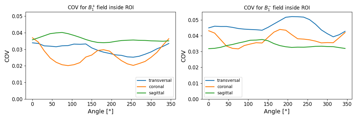
Simulation: Electromagnetic field simulations using the finite integration technique7 were performed in CST Studio Suite 20208 at 63.9MHz. Crucial parts such as length, bore diameter, gradient coil and casing from a commercially available 1.5T whole-body MR scanner were simplified and implemented in the 3D model. Acrylic glass was assigned to insulating parts (εr=2.8, tan(δ)=0.02 (1MHz)). The rotation of the phantom and the RF coil including pad and patient capsule was simulated for all rotation angles from 0° to 360° in increments of 15° (Figure 1) and the transmit (B1+) and receive (B1-) fields were calculated inside the phantom. Transversal, coronal and sagittal slices at the center of the phantom were then obtained and the COV (coefficient of variation: $$$\frac{std.}{mean}$$$) was extracted within a ROI in the center of the slices. The mesh contained 20-50 million cells depending on the rotation of the patient capsule and was refined to a minimal size of 2mm close to the RF coil.
Results
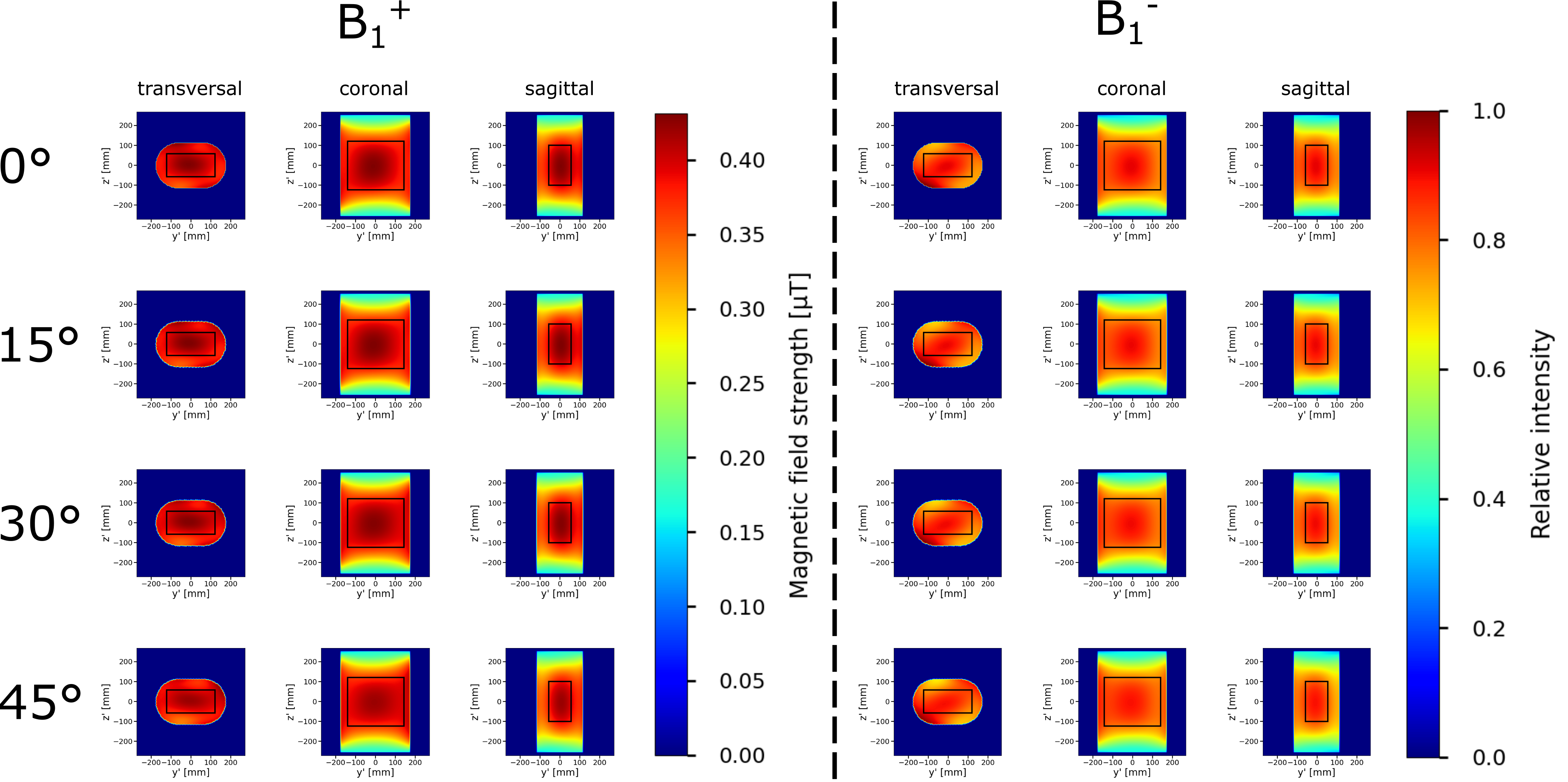
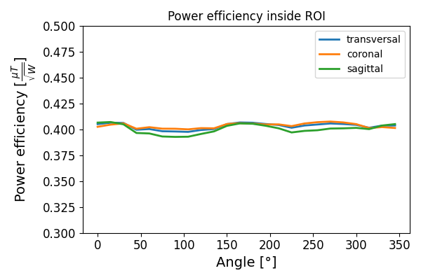
Transmit and relative receive field distributions of the RF coil are shown in Figure 2 for the first 4 rotation angles of the patient capsule. The images indicate good overall homogeneity in all slices of the phantom and the field distributions remain similar for different rotation angles. Minor inhomogeneities are visible close to the edges of the phantom. Figure 3 illustrates the dependency of the uniformity of transmit and receive fields within the highlighted ROI on the rotation angle. Except for the sagittal slice, the transmit field appears to be slightly more homogeneous (lower COV value) than the receive field. Figure 4 shows the power efficiency inside the ROI demonstrating uniform efficiency for all rotation angles.Discussion & Conclusions
The simulated coil offers a solution for MRgRT with particles and provides good homogeneity with high power efficiency independent of the rotation of the patient capsule enabling flexible treatment planning from multiple angles even with a fixed ion source. Slight asymmetries in the transmit and receive characteristics can be related to those reported in literature9,10. In future, phantom MRI measurements should be performed with the experimental setup to confirm the simulated results.Acknowledgements
This work received financial support from the German Federal Ministry of Education and Research (BMBF, ARTEMIS project WP8, funding reference 13GW0436)References
1Pollard, J. M. et al., "The future of image-guided radiotherapy will be MR guided", The British Institute of Radiology (2017)
2Hoffmann A., et al., "MR-guided proton therapy: a review and a preview", Radiation Oncology 15 (2020); 1-13
3Dietrich K. A. et al., "Comparison of birdcage resonator designs for clinical MR-guided radiotherapy", Proceedings Intl. Soc. Mag. Reson. Med. 29 (2021)
4Dietrich K. A. et al., "Construction of a Tx/Rx body coil on a rotatable patient capsule for MR-guided particle therapy", Proceedings Intl. Soc. Mag. Reson. Med. 30 (2022)
5Tropp J., "The theory of the bird-cage resonator", Journal of Magnetic Resonance (1989); 82:51-62
6Hayes C. E. et al., "An efficient, highly homogeneous radiofrequency coil for whole-body NMR imaging at 1.5T", Journal of Magnetic Resonance (1985); 63:622-628
7Weiland T., "A discretization method for the solution of Maxwell’s equations for six-component fields", Electronics and Communications AEU (1977); Vol. 31, No. 3, 116-120
8CST Studio Suite 2020, Dassault Systèmes, Vélizy-Villacoublay, France
9Vaidya M. V. et al., "Dependence of B1+ and B1- field patterns of surface coils on the electrical properties of the sample and the MR operating frequency", Concepts in Magnetic Resonance Part B (2016); 46:25-40
10Cloos M. A. et al., "Multiparametric imaging with heterogeneous radiofrequency fields", Nature Communication (2016); 7:12445
Figures