4261
Simulations of an integrated RF/wireless neonatal head coil array for multiple-input multiple-output (MIMO) wireless MRI data transmission1Medical Physics Graduate Program, Duke University, Durham, NC, United States, 2Brain Imaging Analysis Center, Duke University, Durham, NC, United States, 3GE Healthcare, Aurora, OH, United States
Synopsis
Keywords: Non-Array RF Coils, Antennas & Waveguides, RF Arrays & Systems, WIFI, wireless, neonatal
Neonatal neuroimaging can be significantly improved using a form-fitting, lightweight coil array that is untethered from the scanner for a high SNR and reduced setup time. An iRFW coil array does this by performing simultaneous RF signal acquisition and wireless data transfer with the same coil element. Proof-of-concept simulations of a form-fitting soccer-ball geometry 16-channel iRFW coil head array show a high and uniform SNR in the neonatal head and WIFI 6 antenna gain patterns that radiate power outside the bore using a 2x1 multiple-input multiple-output WIFI 6 scheme for the high data rate wireless transmission of MRI data.
Introduction
Neonatal MRI is used to assess the impact of early disruptions in brain development that can cause long-term neurodevelopment disorders1. These scans are often performed with adult-sized radiofrequency (RF) head coil arrays with coil elements far from the subject, giving a lower signal-to-noise ratio (SNR). Additionally, these arrays are tethered to the scanner via a heavy semi-rigid cable assembly constructed of RF coaxial cables, wires, and cable traps that limit its ease of use. Alternatively, a form-fitting flexible lightweight RF neonatal coil array could be used to provide a higher SNR because the coil elements are next to the subject2,3. Ideally, this coil array would also wirelessly transmit the MRI data outside of the scanner bore instead of through the cable assembly to drastically decrease weight and improve usability.Recently, a novel integrated RF/wireless (iRFW) coil design has been proposed for simultaneous MR signal reception and wireless data transfer with the same coil element by allowing RF currents at the Larmor frequency and in a wireless communication band to flow on its conductors4-6 (Fig. 1). This design has been used to wirelessly transmit ultrasound data at a low data rate from within the scanner bore to the console room via an access point (AP) placed on the scanner room wall7. Similarly, the iRFW coil(s) in a neonatal array could be used to wirelessly transmit MRI data outside of the scanner bore to an AP, but at a higher data rate8,9. Fortunately, new wireless WIFI 6 technologies are available using multiple-input multiple-output (MIMO) antenna designs that significantly increase the wireless data rate (e.g., > 800 Mbps) but have transceivers with high receiver sensitivities, RWIFI6 ~ -60 dBm. For this, the iRFW coil antenna gain, GiRFW, can be optimized in the bore by determining a diameter and position in the array that limits interactions with the bore and maximizes the power to the AP, which must be above RAPWIFI6 to avoid wireless data loss. Mathematically, the difference between GiRFW , which is attenuated between the coil and AP (i.e. path loss), and RAPWIFI6 must be positive to avoid data loss (i.e., link budget). In this work, we perform simulations of a neonatal iRFW head coil array in a scanner bore (Fig. 2) to provide both a high SNR in an infant’s head and the best link budget for reliable MIMO (2 iRFW coil elements x 1 AP) WIFI 6 wireless data transfer.
Methods
A 16-channel neonatal iRFW head coil array placed near a 50-cm infant was modeled with six 5.2-cm and ten 6.9-cm diameter coil elements (Fig 2), each having three 10-pF lumped capacitors and two RF excitation ports resonant at 127.7 MHz (3T MRI) and 5.5 GHz (WIFI 6) to generate the RF currents for simultaneous imaging and wireless data transfer. These coil diameters can be overlapped to decouple adjacent coil elements for a uniform image SNR and have the correct circumference (i.e., C5.2mm~3𝝀WIFI, C6.9mm~4𝝀WIFI) to provide high antenna gain to the AP. The MRI and WIFI ports were RF-isolated by inserting high-impedance band-stop filters resonant at 5.5 GHz and 127.7 MHz between these ports and the coil element, respectively. A 70-cm diameter scanner bore was then modeled as a cylindrical two-layer impedance boundary that is electrical equivalent to a 2-mm thick copper conductor bonded to a 5-cm thick FR4 epoxy bore. Finally, the AP was modeled as a 5.5-GHz dipole antenna located 3m behind the scanner isocenter to determine the link budget between the iRFW coil elements and the AP.Finally, a set of finite-element simulations were performed with the model to determine the average SNR and SNR coefficient of variance (COV = stdev/mean) in the phantom head. Additionally, the principal plane WIFI gain patterns and the link budget between the iRFW coil elements to the AP were determined to assess the wireless performance of the array in the bore. For each simulation, two coil elements of either diameter at new locations in the array were chosen to be iRFW coil elements while the remaining 14 were conventional RF coil elements.
Results
Figure 2 shows the iRFW coil array had a uniform SNR in the head with average SNR values of 261.1, 226.7, 244.3 and SNR COV values of 0.43, 0.53, 0.44 in the axial, coronal, and sagittal planes, respectively.Figure 3 shows the iRFW coil elements assigned to coils 3 and 4 in the array provided a gain pattern that maximized the power toward the AP and minimized it into the scanner bore. The corresponding path losses to the AP were -50.7 and 49.9 dB, which had the highest link budgets of 9.3 and 10.1 dB of any simulation. Contrastingly, the simulation with iRFW coil elements assigned to coils 13 and 15 provided path losses of -77.8 and -73.9 dB, which will result in data loss.
Conclusion
These simulations show the iRFW coil array can provide a high SNR in the infant's head and gain patterns with link budgets that are sufficient for high throughput wireless MRI data transfer. Interestingly, the iRFW coil design can be further developed into a blanket coil array to wirelessly transmit MR data for head and body neonatal imaging.Acknowledgements
This work was in part supported by NIH S10 OD021480, Ansys Partnership Donation, and GE Healthcare.
References
1. Copeland A, Silver E, Korja R, Lehtola SJ, Merisaari H, Saukko E, Sinisalo S, Saunavaara J, Lähdesmäki T, Parkkola R, Nolvi S, Karlsson L, Karlsson H, Tuulari JJ. Infant and Child MRI: A Review of Scanning Procedures. Front Neurosci. 2021 Jul 12;15:666020. doi: 10.3389/fnins.2021.666020. PMID: 34321992; PMCID: PMC8311184.
2. Cogswell PM, Trzasko JD, Gray EM, Campeau NG, Rossman PJ, Kang D, Robb F, Stormont RS, Lindsay SA, Bernstein MA, McGee KP, Huston J 3rd. Application of Adaptive Image Receive Coil Technology for Whole-Brain Imaging. AJR Am J Roentgenol. 2021 Feb;216(2):552-559. doi: 10.2214/AJR.20.22812. Epub 2020 Nov 25. PMID: 33236945; PMCID: PMC7968701.
3. Zhang, B., Sodickson, D.K. & Cloos, M.A. Publisher Correction: A high-impedance detector-array glove for magnetic resonance imaging of the hand. Nat Biomed Eng 2, 708 (2018). https://doi.org/10.1038/s41551-018-0298-7
4. Darnell D, Cuthbertson J, Robb F, Song AW, Truong TK. Integrated radio-frequency/wireless coil design for simultaneous MR image acquisition and wireless communication. Magn Reson Med. 2019 Mar;81(3):2176-2183. doi: 10.1002/mrm.27513. Epub 2018 Sep 14. PMID: 30277273; PMCID: PMC6347493.
5. Bresticker J, Thompson Z, Willey D, Song AW, Darnell D, Truong TK. Simulations of Integrated Radio-Frequency/Wireless Coil Designs for Simultaneous MR Image Acquisition and Wireless Communication. ISMRM 2019; 19:1541.
6. Cuthbertson JD, Truong TK, Stormont R, Robb F, Song AW, Darnell, D. An iPRES-W Coil Array for Simultaneous Imaging and Wireless Localized B0 Shimming of the Cervical Spinal Cord. Magn Reson Med. 2022;1-13.
7. Willey DA, Dickinson OJ, Overson DK, Truong TK, Fraser R, Song AW, Madore B, Darnell D. Wireless Physiological Motion Monitoring with an Integrated RF/Wireless Coil Array and MR-Compatible Ultrasound-Based System. ISMRM 2022 31, 7295.
8. Darnell D, Truong TK, Song AW. Recent Advances in Radio-Frequency Coil Technologies: Flexible, Wireless, and Integrated Coil Arrays. J Magn Reson Imaging. 2022 Apr;55(4):1026-1042. doi: 10.1002/jmri.27865. Epub 2021 Jul 29. PMID: 34324753.
9. Nohava L, Ginefri JG, Willoquet G, Laistler E, Frass-Kriegl R. Perspectives in wireless radio frequency coil development for magnetic resonance imaging. Front. Phys., 21 February 2020. doi.org/10.3389/fphy.2020.00011
Figures
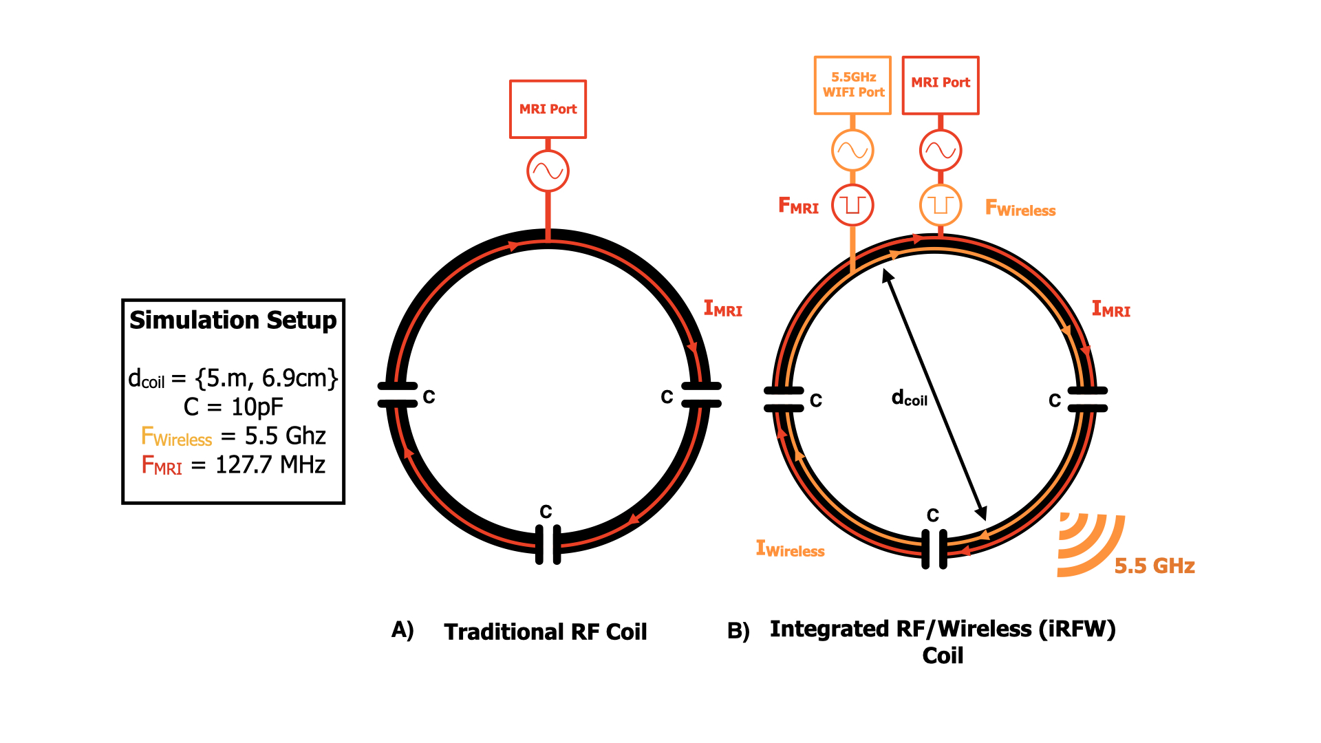
Figure 1. The traditional RF coil (a) allows an RF current to flow for signal reception while the iRFW coil (b) allows RF currents at both the Larmor and WIFI 6 frequencies for simultaneous signal reception and wireless data transfer.
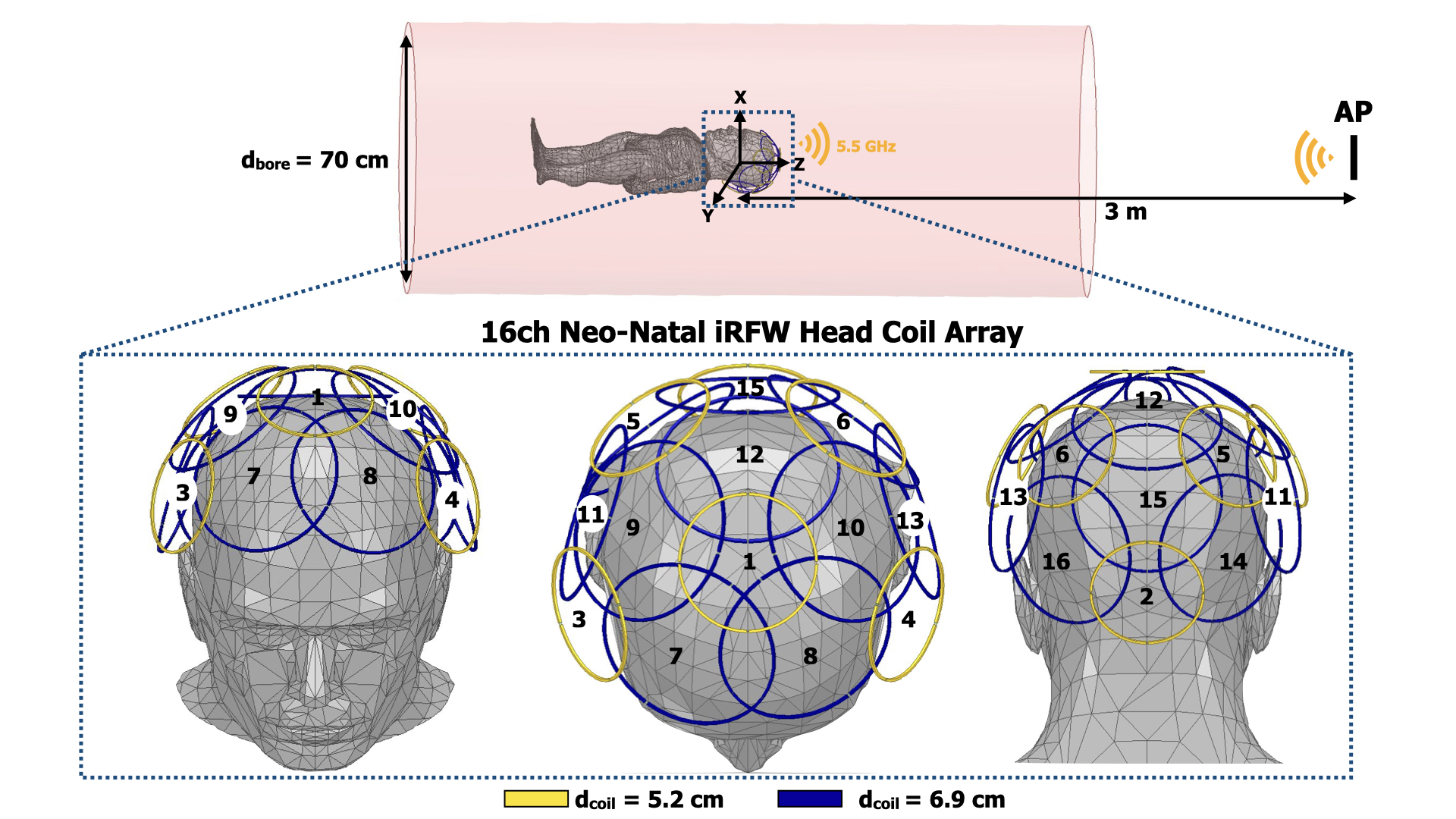
Figure 2. A form-fitting 16-channel soccer-ball iRFW head coil array with coil element diameters of 5.2 cm (yellow) and 6.9 cm (blue) uniformly distributed about the head of neonatal infant and symmetrically about the z-axis of the bore was modeled at the isocenter of a 70 cm diameter bore and 3m away from an AP behind the scanner. The model was used to simulate the SNR inside the head and WIFI 6 wireless gain inside the bore.
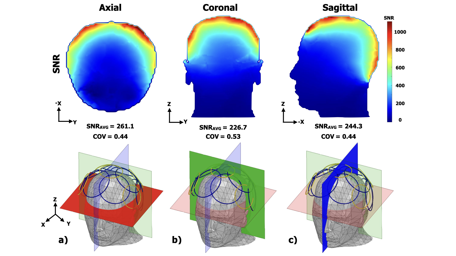
Figure 3. The SNR maps in the axial (a), coronal (b), and sagittal (c) slices showed a high and uniform SNR in the infant model head while both 127.7 MHz and 5.5 GHz RF currents for 3T MRI and WIFI 6 flow on the iRFW coil array for simultaneous image reception and high-data-rate MIMO wireless data transmission.
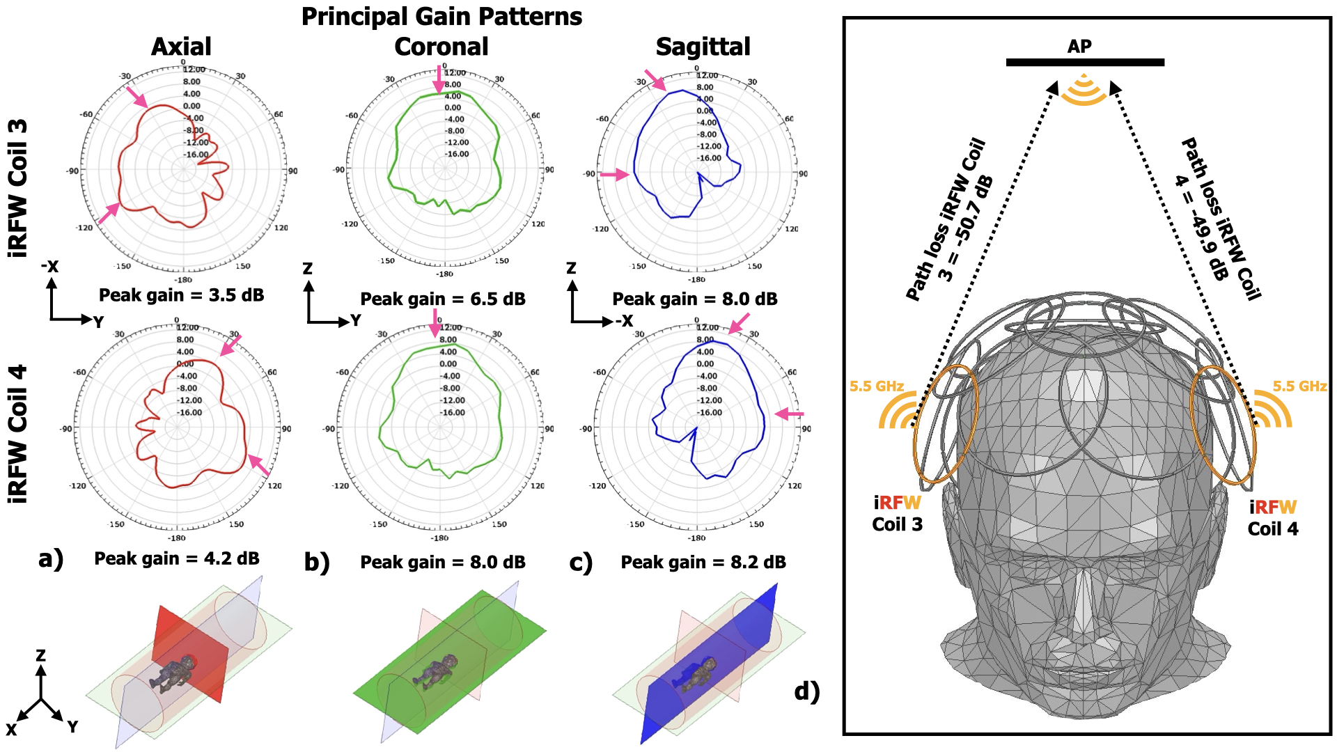
Figure 4. The iRFW coil design assigned to coil elements 3 and 4 in the array had peak gain values GiRFW (pink arrows) in the axial (a) and sagittal (c) principal planes that were directed along opposite sides of the bore but toward the AP. The peak gain values in the coronal plane (b) were both directed line-of-sight to the AP, which resulted in a low path loss and the highest link budget (d) for all simulations.