4256
Numerical investigation of multi-turn wireless RF coil for MRI
Ming Lu1, Xiaoyang Zhang1, and Xinqiang Yan2,3
1College of Nuclear Equipment and Nuclear Engineering, Yantai University, Yantai, China, 2Vanderbilt University Institute of Imaging Science, Vanderbilt University Medical Center, Nashville, TN, United States, 3Department of Radiology and Radiological Sciences, Vanderbilt University Medical Center, Nashville, TN, United States
1College of Nuclear Equipment and Nuclear Engineering, Yantai University, Yantai, China, 2Vanderbilt University Institute of Imaging Science, Vanderbilt University Medical Center, Nashville, TN, United States, 3Department of Radiology and Radiological Sciences, Vanderbilt University Medical Center, Nashville, TN, United States
Synopsis
Keywords: Non-Array RF Coils, Antennas & Waveguides, RF Pulse Design & Fields
Standard RF coils require preamplifier models, baluns, coil plugs, and coil ID circuits, which makes coils bulky and expensive. A more affordable way to achieve as high SNR as the standard local receive coil is using the inductively coupled wireless coil. In this work, we numerically investigate whether the multi-turn wireless coil with a similar structure as the stacked coil can enhance the SNR.Introduction:
Radio frequency (RF) coil is an important part of MRI system, which directly determines the imaging quality. Standard RF coils require preamplifier models, baluns, coil plugs, and coil ID circuits, which makes coils bulky and expensive. A more affordable way to achieve as high SNR as the standard local receive coil is using the inductively coupled wireless coil [1-6]. For the wireless coil, the mutual coupling with the body coil is crucial to the signal transmission efficiency and thereby the SNR. Recently, it is found that a wireless RF coil with two stacked loops can significantly improve the SNR compared with a single-loop wireless coil [6]. However, the stacked coil requires capacitive decoupling which is complicated and laborious in practice. It also faces challenges in multi-coil design and may not be feasible in volume-type wireless coil. In this work, we numerically investigate whether the multi-turn wireless coil with a similar structure as the stacked coil can enhance the SNR.Method:
We first simulated a 2-turn and 3-turn spiral wireless coil (Figure 1B-1C) and compared them to a single-loop coil (Figure 1A). The outer dimension of all coils is 20 x 20 cm2 and the width of conductors is 0.635cm (1/4 in). The gap between adjacent loops is set to the same as the width of conductor (0.635 cm). To further investigate how the gap affects the coil performance, we also investigate a set of 2-turn and 3-turn coils with the same dimension but a larger gap of 1.27 cm (i.e., 1/2 in), as shown in Figures 1D-1E. Figures 1F-1J showed the simulation models of all scenarios, with a 20-cm-diameter sphere phantom as the loading (σ = 0.6 S/m and ξr = 78). We also investigated how the coil-to-phantom distance affects the SNR (from 1 cm to 4 cm). All coils were designed for 3T scanners (Larmor frequency of 128 MHz). To further explore the possible benefit in human imaging, we simulated a multi-turn wireless coil with the optimal parameters and compared to it to the body coil (Figure 2). Electromagnetic (EM) simulations were performed using a commercial FEM-based solver (Ansys HFSS). The body coil was modeled as a 16-rung quadrature high-pass birdcage coil with a diameter of 60 cm and a length of 60 cm. The body coil was well tuned, matched and decoupled using RF circuit and 3D EM co-simulation method [7]. For the wireless coil, they were finely tuned to the desired frequency (128 MHz) by maximizing the resonate peak of a double-probe, which is similar to the practical procedure.Results:
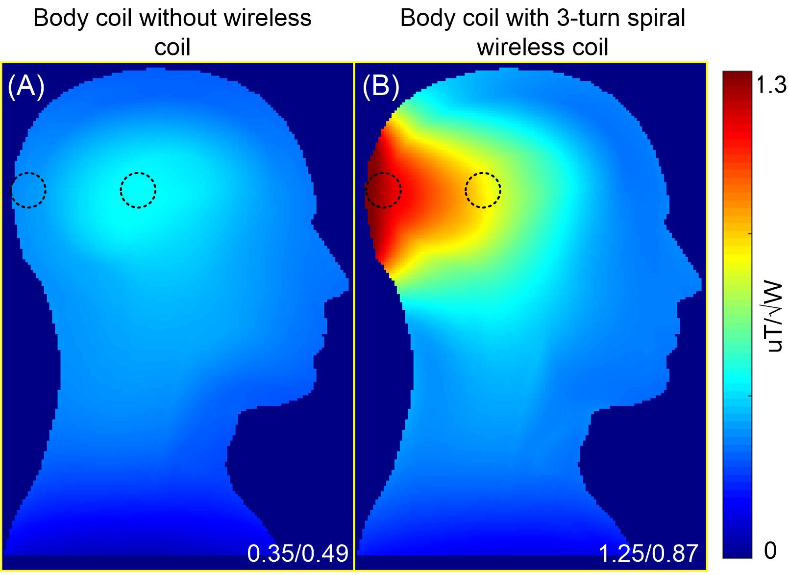
Figure 3 plots the resonant peaks of single-loop, 2-turn, and 3-turn spiral wireless coils with different coil-to-phantom distances and different gaps between turns. All coils were well tuned to 128 MHz, providing the foundations for a fair comparison. Figure 4A shows the normalized B1- maps of all wireless coils on central axial slices. B1- efficiency increases as the turn of the spiral wireless coil increases, and it decreases as the distance between the coil and the phantom increases. It is noticed that multi-turn coils with a larger gap exhibit a higher B1- efficiency at the surface area, which could be attributed to the fact that they have smaller inner loops. Figure 5 compares the B1- efficiency on a human head using the body coil without and with a 3-turn spiral wireless coil. The 3-turn spiral wireless coil show significant B1- efficiency improvement (up to 3.6 times) at both the surface and center area (0.87 vs. 0.49).Conclusion:
We investigated a set of multi-turn wireless coils and found that the multi-turn design could indeed further increase the SNR compared to a single-loop design. Unlike the complex stacked coil in Lu et al [6], this multi-turn coil is still a single resonator and does not require any decoupling treatments. We believe the mechanism lies in the fact that a multi-turn structure could increase the mutual coupling between the local wireless coil and the body coil, i.e., the power/signal transmission efficiency. Further studies will be needed to validate the numerical results and to explore the possibility of wireless coils with multiple elements as well as multiple turns.Acknowledgements
National Natural Science Foundation of China,Grant/Award Number: 11905181References
- Sahara T, Hashimoto S, Tsutsui H, et al. Development of Inductively Coupled Wireless Radio Frequency Coil for Magnetic Resonance Scanners. 2007 Inaugural IEEE-IES Digital EcoSystems and Technologies Conference. IEEE, 2007: 464-467.
- Shchelokova A V, van den Berg C A T, Dobrykh D A, et al. Volumetric wireless coil based on periodically coupled split‐loop resonators for clinical wrist imaging. Magnetic resonance in medicine, 2018, 80(4): 1726-1737.
- Nohava L, Ginefri J C, Willoquet G, et al. Perspectives in wireless radio frequency coil development for magnetic resonance imaging. Frontiers in Physics, 2020, 8: 11.
- Alipour A, Seifert A C, Delman B N, et al. Improvement of magnetic resonance imaging using a wireless radiofrequency resonator array. Scientific reports, 2021, 11(1): 1-12.
- Okada T, Handa S, Ding B, et al. Insertable inductively coupled volumetric coils for MR microscopy in a human 7T MR system. Magnetic Resonance in Medicine, 2022, 87(3): 1613-1620.
- Lu M, Chai S, Zhu H, et al. Low‐cost inductively coupled stacked wireless RF coil for MRI at 3 T. NMR in Biomedicine, 2022: e4818.
- Kozlov M, Turner R. Fast MRI coil analysis based on 3-D electromagnetic and RF circuit co-simulation. Journal of magnetic resonance, 2009, 200(1): 147-152.
Figures
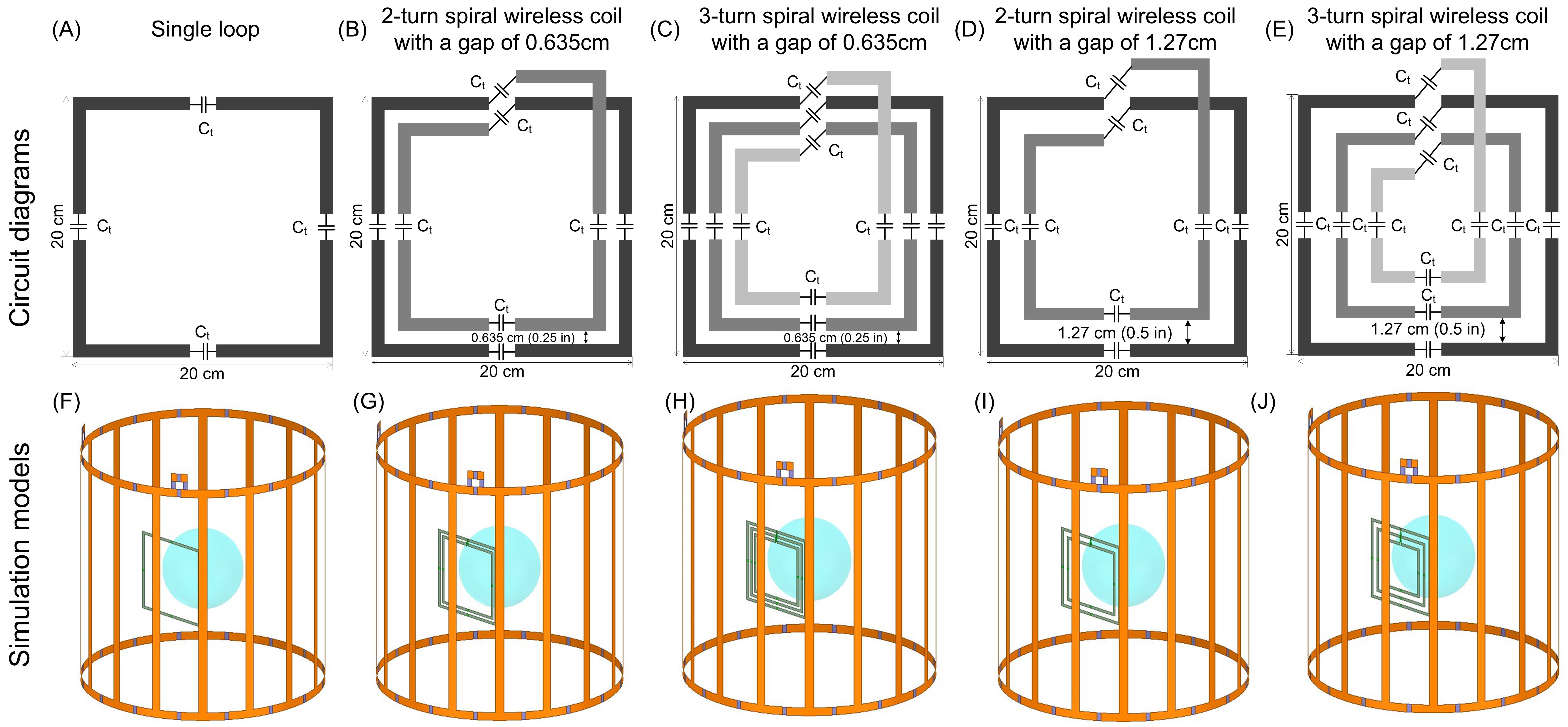
Figure
1. A–E: Circuit diagrams of a single-loop wireless coil (A), a 2-turn spiral
wireless coil with 0.635 cm gap (B), a 3-turn spiral wireless coil with 0.635cm
gap (C), a 2-turn spiral wireless coil with 1.27 cm gap (D), and a 3-turn
spiral wireless coil with 0.635 cm gap (E). F–J: Simulation models of the body
coil with various wireless coils on the phantom.
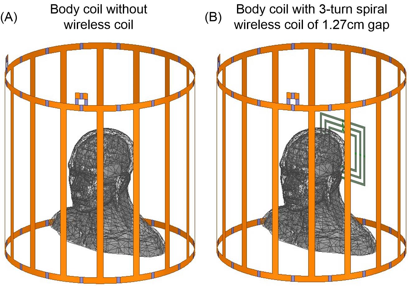
Figure
2. Simulation models of the body coil without (A) and with (B) a 3-turn wireless
coil underneath the human head.
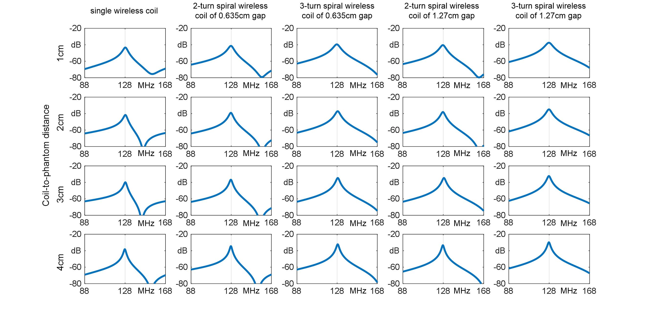
Figure
3. Resonant peak of all wireless coils. A pair of 3-cm-diameter pick-up probes
is placed 1cm above the wireless coil to detect the resonate peak.
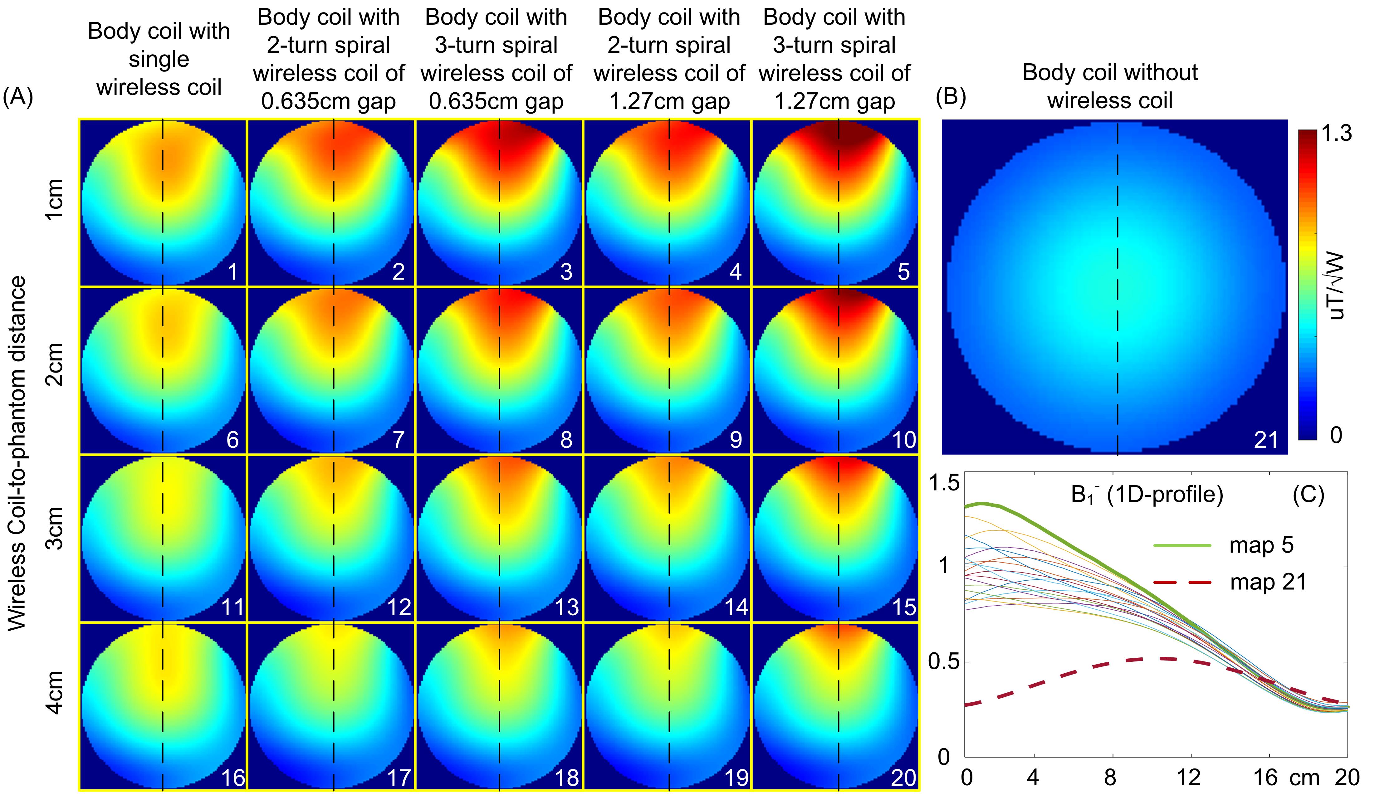
Figure
4. Simulated axial B1- maps in the phantom using the body coil with various wireless coils (A) and
without any wireless coil (B). (C): 1D profiles of B1- along
the black-dotted lines in Figure 4A and 4B.
Figure
5. Simulated sagittal B1-
maps using the body coil without wireless coil (A) and with a 3-turn spiral
wireless coil (B) on the human head. Average B1-
efficiency at the surface and center is marked in in the bottom right corner of
the figure.
DOI: https://doi.org/10.58530/2023/4256