4255
Performance and B1 Efficiency Analysis of Different Dipole Antenna Types at 7T.1Department of Biomedical Engineering, State University of New York at Buffalo, Buffalo, NY, United States
Synopsis
Keywords: Non-Array RF Coils, Antennas & Waveguides, Simulations
In this work, we compare the performance of several dipole antenna types for MR applications at 7T in terms of quality factor, B1+ strength, SAR, B1+ field pattern, and B1+ efficiency. This study may provide guidance on the selection of an appropriate dipole coil for a specific imaging application.
Introduction
The dimensional constraints of conventional dipole antennas limited their usage in MR imaging until novel designs were introduced, such as incorporating meander components to compact the dipoles while preserving electrical length to tune at the required frequency. Adding meanders on each end, completely meandered dipole arms, and adding meander fractions over the length of each dipole arm are all examples of meander dipoles. The meander approach makes it simple to tune shorter dipoles at ultra-high field strengths like 7T1-3. Our previous studies presented two dipole antenna designs based on coating the dipole arms with high dielectric constant materials to contribute to attempts to make dipoles more design friendly and easy to use in applications intended for smaller area MR imaging applications. Fully dielectric material coated (FDMC) and discretely dielectric material coated (DDMC) dipole antennas were proposed4-8. We previously compared our designs to conventional dipole antennas, but the designs should also be thoroughly compared with the widely used meander dipole designs to understand which design performs better in significant aspects and if the comparison sheds more light on possible changes that can be made to the proposed designs to benefit MR imaging at ultra-high-field strength further.Method
We set the length of each design to 25 cm for comparison. Other tuning parameters, such as meander length and width for meander-based designs, the relative permittivity of the high dielectric constant material, and material thickness for dielectric material coating-based designs, were modified to tune each design at 300MHz. Fig1a shows the dipole types and dimensions for each design. The field strengths and distributions were evaluated using a cylindrical phantom with a length of 50cm and a radius of 10cm.The following material qualities were assigned to the phantom: relative permittivity εr:50,electrical conductivity σ:0.6 S/m. Fig1b shows the phantom, the positioning of each design, and the distance between them. The materials that coat the FDMC and DDMC dipoles have relative permittivity values of 1000 and 900, respectively. To determine the tuned frequency, a frequency sweep was performed. In addition, frequency domain studies were performed to analyze the B1+ and SAR maps produced by individual design. We estimated the B1+ efficiency of each design based on the peak B1+ and SAR data by dividing the peak B1+ by the peak SAR for the respective design.Results
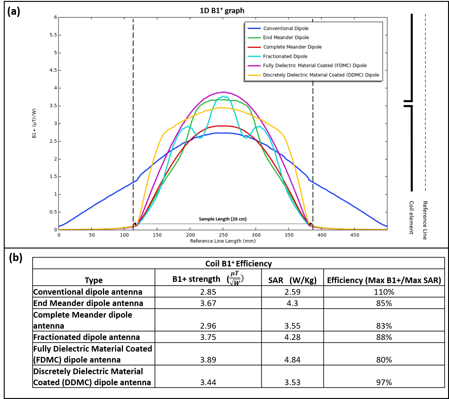
Fig2 Shows each design's evaluated S-parameters 1D profile in free space and loaded case. It also includes the Q-factor values and the parameters such as 3dB bandwidth frequencies and center frequency highlighted in each case. In comparison, the DDMC dipole antenna had the highest Q-factor of 163.04 and 85.18 among all the designs in free space and loaded case, respectively. The transverse and sagittal B1+ maps in the cylindrical phantom can be seen in Fig3a & Fig3b, respectively. FDMC dipole produced the highest peak B1+ strengths, followed by the Fractionated and End-meander dipole. Further, the transverse SAR maps are shown in Fig4. The FDMC, End Meander, and Fractionated dipole generated the highest SAR values, respectively, while the conventional dipole produced the lowest SAR values. The 1D profiles of the B1+ values produced by each design along a 50 cm reference line which was 1.5 cm away, can be seen in Fig5a. The reference line schematic relative to the coil element is also shown in Fig5a. Based on the field patterns, it is evident that although the DDMC did not generate a higher amplitude, it produced flatter fields with more coverage in the phantom. The 1D profile also shows the 25 cm long region of interest to be imaged, and most of the B1+ fields produced by conventional dipole are unutilized. Finally, Fig5b shows the peak B1+ , SAR values, and the calculated efficiency for each design in a tabulated form. The conventional dipole produced the highest B1+ efficiency of 110%, followed by the DDMC dipole with 97%.Discussion/Conclusion
We compared the conventional, end meander, complete meander, fractionated, Fully dielectric material coated (FDMC), and Discretely dielectric material coated (DDMC) dipole designs based on the Q-factor, B1+ values, B1+ field patterns, SAR values, and the B1+ efficiency. Our results show that the DDMC dipole antenna is more favorable due to the flatter fields and the higher coverage than the other designs. Further, the B1+ efficiency for the DDMC dipole was 97%, which was highest in the conventional dipole alternative designs. Further, the Fractionated, FDMC, and End meander dipoles produced the highest peak B1+ values and a field pattern that can be used in MR applications requiring higher penetration. The FDMC and DDMC dipole antennas require minor modifications to the dipole's conductor arms and are more compact to be arranged in multi-channel array systems than the meander designs.Acknowledgements
This work is supported in part by the NIH under a BRP grant U01 EB023829 and by the State University of New York (SUNY) under the SUNY Empire Innovation Professorship Award.
References
1. Raaijmakers AJ, Luijten PR, van den Berg CA. Dipole antennas for ultrahigh-field body imaging: a comparison with loop coils. NMR Biomed. 2016 Sep;29(9):1122-30. doi: 10.1002/nbm.3356. Epub 2015 Aug 17. PMID: 26278544
2. Raaijmakers AJ, Italiaander M, Voogt IJ, Luijten PR, Hoogduin JM, Klomp DW, van den Berg CA. The fractionated dipole antenna: A new antenna for body imaging at 7 Tesla. Magn Reson Med. 2016 Mar;75(3):1366-74. doi: 10.1002/mrm.25596. Epub 2015 May 2. PMID: 25939890.
3. Rupprecht S, Sica CT, Chen W, Lanagan MT, Yang QX. Improvements of transmit efficiency and receive sensitivity with ultrahigh dielectric constant (uHDC) ceramics at 1.5 T and 3 T. Magn Reson Med. 2018;79(5):2842-2851. doi:10.1002/mrm.26943
4. Wang C, Zhang X. Evaluation of B1+ and E field of RF Resonator with High Dielectric Insert. ISMRM p3054 (2009)
5. Bhosale AA, Gawande D, Zhang X. B1 field flattening and length control of half-wave dipole antenna with discrete dielectric coating. Proceedings of the International Society for Magnetic Resonance in Medicine ... Scientific Meeting and Exhibition. International Society for Magnetic Resonance in Medicine. Scientific Meeting and Exhibition. 2022 May;30:4104. PMID: 36071703; PMCID: PMC9445060.
6. Bhosale AA, Gawande D, Zhang X. A Dielectric Material Coated Half-Wave Dipole antenna for Ultrahigh Field MRI at 7T/300MHz. Proc Int Soc Magn Reson Med Sci Meet Exhib Int Soc Magn Reson Med Sci Meet Exhib. 2022 May;30:4103. PMID: 36071701; PMCID: PMC9445058.
7. Bhosale, A., L. Ying, and X. Zhang. A 15-channel End-coated Half-wave Dipole Antenna Array System for Foot/Ankle/Calf Imaging at 7T. in Proceedings of the Annual Meeting of ISMRM 2022. 2022. London, UK.
8. Bhosale AA, Ying LL, Zhang X. An 8-Channel High-permittivity Dielectric Material-Coated Half-Wave Dipole Antenna Array for Knee Imaging at 7T. Proc Int Soc Magn Reson Med Sci Meet Exhib Int Soc Magn Reson Med Sci Meet Exhib. 2022 May;30:4105. PMID: 36071705; PMCID: PMC9445071.
Figures
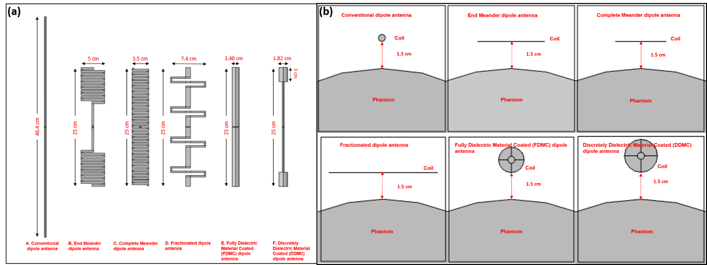
Figure 1. (a) The Dipole antenna types with the dimensions used for the performance analysis (b) Transverse view of each coil's placement around the phantom for the loaded case and the distance between the phantom and the coil.
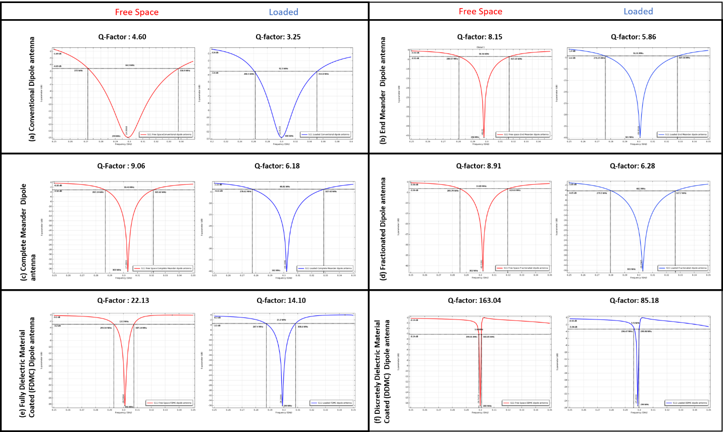
Figure 2. The figure shows S-parameters plots for the free space, the loaded case of each dipole design, and the labeled data on the plots used for Q-factor calculation.
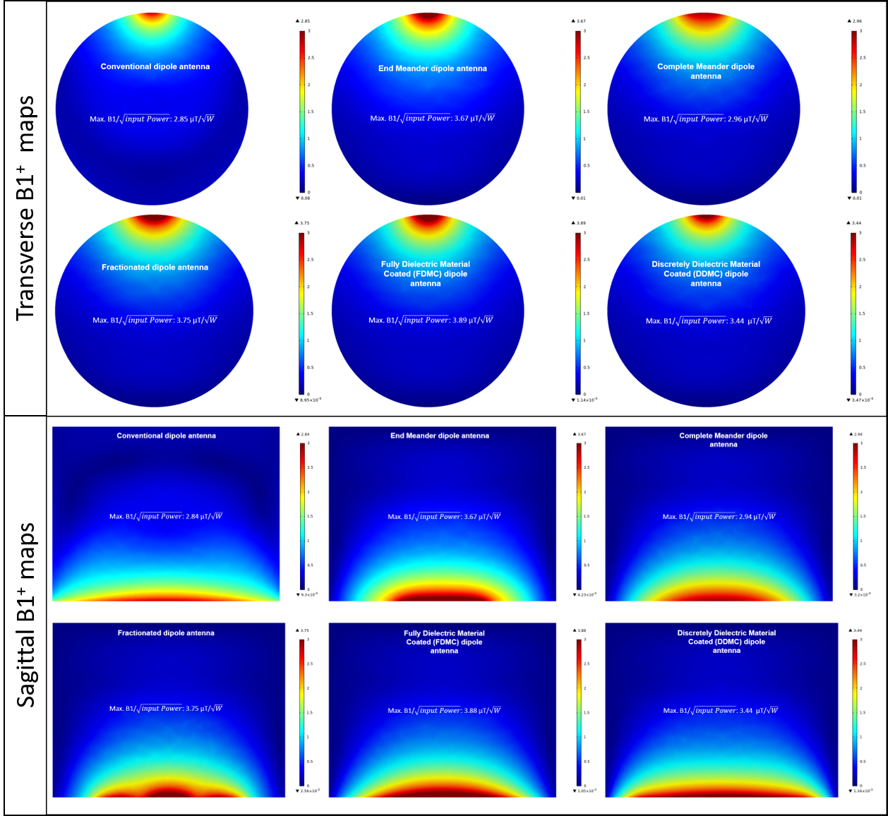
Figure 3. B1+ maps produced by each design in transverse and sagittal planes of the phantom. The unit is expressed in μT/√W. The figure also shows the peak values listed on each map.
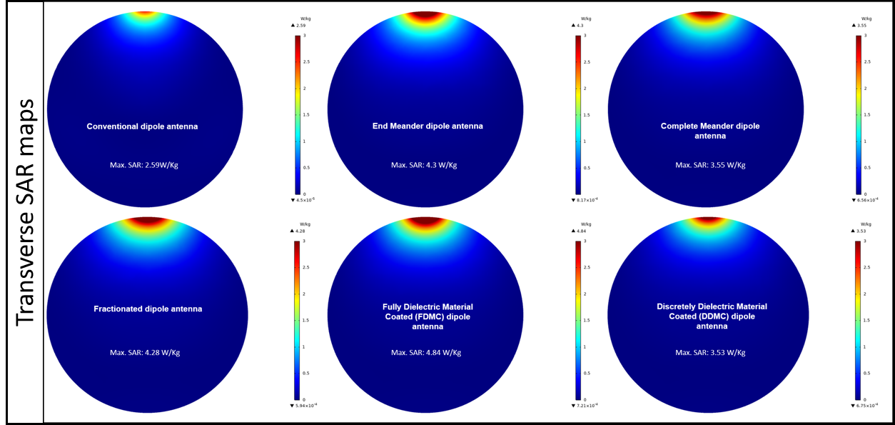
Figure 4. The figure shows the SAR maps in the transverse plane of the phantom. The unit is expressed in W/Kg. The figure also shows the peak values listed on each map.