4254
Determination of the Optimum Permittivity of High-Permittivity Pads when Dipoles are Used as Transmit Coils for the Chest
Giuseppe Carluccio1,2 and Christopher Michael Collins1,2
1Radiology, NYU Grossman School of Medicine, New York, NY, United States, 2Center for Advanced Imaging Innovation and Research (CAI2R), New York University, New York, NY, United States
1Radiology, NYU Grossman School of Medicine, New York, NY, United States, 2Center for Advanced Imaging Innovation and Research (CAI2R), New York University, New York, NY, United States
Synopsis
Keywords: RF Arrays & Systems, RF Arrays & Systems, High-Permittivity Materials
High-Permittivity Materials are often used to manipulate the radiofrequency field B1. Optimization of the permittivity depends on the geometry of the pad, of the subject and of the coil. In this work we determine the permittivity of two pads positioned around the torso, having thickness 1.5 cm and 3 cm, when a dipole array is used to provide the highest transmit efficiency in the heart. The pads provide an improvement of the transmit efficiency of 9.5% and 7.6% for the 1.5 cm and 3cm case respectively, while providing a SAR reduction of 20.2% and 12.5%.Introduction
High-Permittivity Material (HPM) Pads are often used in MRI to manipulate the radiofrequency field $$$B_1$$$. For example, they have shown significant improvements in the SNR distribution, transmit efficiency and field homogeneity both in simulations and experiments1,2 . HPM have often been used in applications to improve the $$$B_1$$$ field in the head3-5 , but interest is also growing to manipulate the $$$B_1$$$ field in other body parts, such as the heart6,7. However, different frequencies and geometries of both the coils and the subjects affect the field distributions. Therefore, when HPM pads are used to control the fields in tissues with different shapes, new optimum values of permittivity and geometry of the pads (such as the thickness) need to be determined. For example, the optimum permittivity was calculated when the HPM pads are used to maximize the SNR and the transmit efficiency in the heart7 . In that publication an array of 8 TEM coils was used to transmit the $$$B_1$$$ field, and two optimum permittivity values were found for two different thicknesses of the pads, 1.5 cm and 3 cm. In the same publication, the performance of those optimum values was evaluated when dipole antennas are used to transmit the fields, and it was found that dipoles provided a better transmit efficiency and maximum SAR than TEM coils, even though the permittivity values were optimized for TEM coils. In this work, we performed a procedure to determine the optimum permittivity of the HPM pads that would improve the transmit efficiency in the heart.Methods
The determination of the optimum permittivity values was performed using electromagnetic simulations. Two HPM pads were symmetrically positioned around the chest of the human body model Duke of the Virtual Family8 with a 5 mm isotropic resolution. An 8-channel transmit array with 16 cm long dipole antennas was positioned on top of the pads. The array elements were split into a clamshell configuration so that 4 were positioned on top of the torso and 4 on the back. The shape of the HPM pads is conformal with the position of the dipoles. We determined the optimum permittivity value for two thicknesses of the pads: 1.5 cm and 3 cm (Figure 1). For each pad thickness we calculated the electromagnetic fields for 6 different permittivity values: 1, 25, 50, 75, 100, and 60 which corresponded to the optimum permittivity found for the TEM coils with the 3 cm thick pad. In addition, we also computed the electromagnetic fields when no pad is used and the dipoles are positioned at a minimum distance from the body. For each case, the electromagnetic fields were computed and normalized so that the average $$$B_1^+$$$ in the heart is equal to 1 μT, and the corresponding transmit efficiency and 10g average SAR is computed. The electromagnetic fields were computed with commercial software (xFDTD; Remcom), and postprocessing was performed with MATLAB (the Mathworks).Results
The transmit efficiency ratios with respect to the case with no pad for the different permittivity values are reported in Figure 2, while the maximum 10g average SAR values are reported in Figure 3. The transmit efficiency and SAR values for the case with no pad are also reported in Figure 2 and Figure 3 with a dashed green line. For the examined cases, the permittivity values providing the maximum transmit efficiency are εr=60 for the 1.5 cm thickness, and εr=25 for the 3 cm thickness,. With respect to the case with no pad used, optimum HPM pads provided an improvement of the transmit efficiency of 9.5% and 7.6% for the 1.5 cm and 3 cm case respectively, and at the same time providing a SAR reduction of 20.2% and 12.5% for the 1.5 cm and 3 cm case respectively. Figure 4 reports the $$$B_1^+$$$ field distributions and the 10g average SAR profile for an axial view.Discussion
Strategic use of HPM pads can provide notable increase in transmit efficiency and significant decrease in maximum local SAR when imaging the heart with dipole antennas at 7T, as it can be observed in Figure 4. Optimum permittivities for the dipole configurations are different from the ones found when the TEM coils are used as a transmit array7, which confirms that the permittivity must be optimized for each coil geometry. The optimum solutions provide a significant improvement with respect to the case when no pad is used and the coils are positioned at minimum distance from the body. The transmit efficiency and SAR optimization curves in Fig. 2 and 3 are smoother for the 1.5cm case, while more frequent and wider fluctuations are observed for the 3cm case. For example, for the 3cm case the maximum SAR for εr=75 is more than 4 times higher than the permittivity value εr=50, which provides the minimum value of the curve in Figure 3.Acknowledgements
This work was performed under the rubric of the Center for Advanced Imaging Innovation and Research (CAI2R, www.cai2r.net) at the New York University School of Medicine, which is an NIBIB Biomedical Technology Resource Center (NIH P41 EB017183).References
- Webb, Conc. Magn Reson A, 2011 Jul;38(4):148-84.
- O’Brien et al., J Magn Reson Imaging. 2014 Oct;40(4):804-12.
- Sica et al., Magn Reson Med. 2020 Mar;83(3):1123-34.
- Lakshmanan et al., Magn Reson Med. 2021 Aug;86(2):1167-1174
- Gandji et al., Magn Reson Med, 2021 86:3292–3303
- De Heer et al., Magn Reson Med, 2012 Oct; 68(4):1317-24.
- Carluccio et al., Magn Reson Mat in Phys, Bio and Med. 2022 May;31:1-7.
- Christ et al., Phys Med Biol. 2010;55:N23- N38
Figures
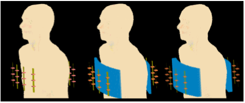
Figure 1. Geometry of the problem: case of no pad and closest dipoles to the body (left), case with 1.5 cm thick pad (middle), and case with 3 cm thick pad (right). Dipole elements (green) each contain three breaks (orange) to simulate a center-feed dipole antenna.
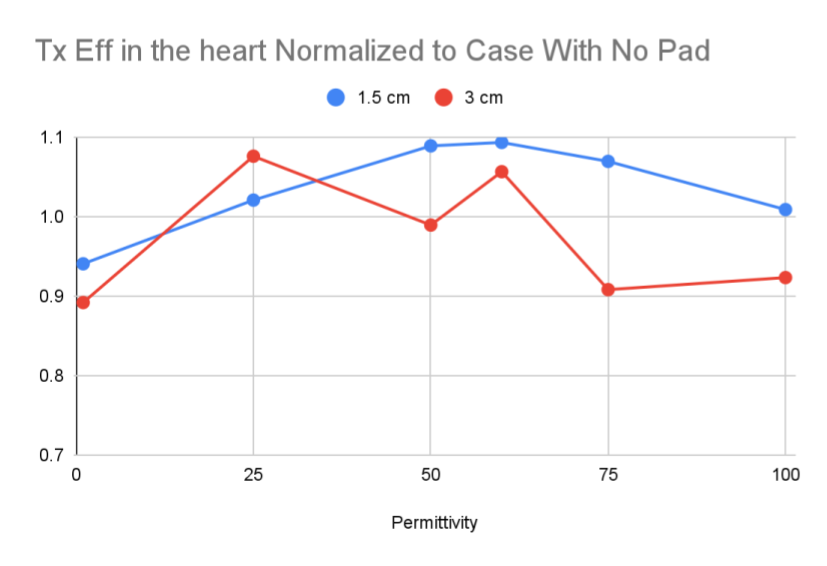
Figure 2. Ratio of the average transmit efficiency in the heart to the value observed when no pad is present, as a function of permittivity in the 1.5 cm thick pad (blue line) and 3 cm-thick pad (red line).
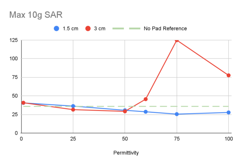
Figure 3. Values of the maximum 10g average SAR as a function of permittivity in the 1.5 cm thick pad (blue line) and 3 cm-thick pad (red line). The green dashed line represents the maximum 10g average SAR value observed in the case when no pad is present.
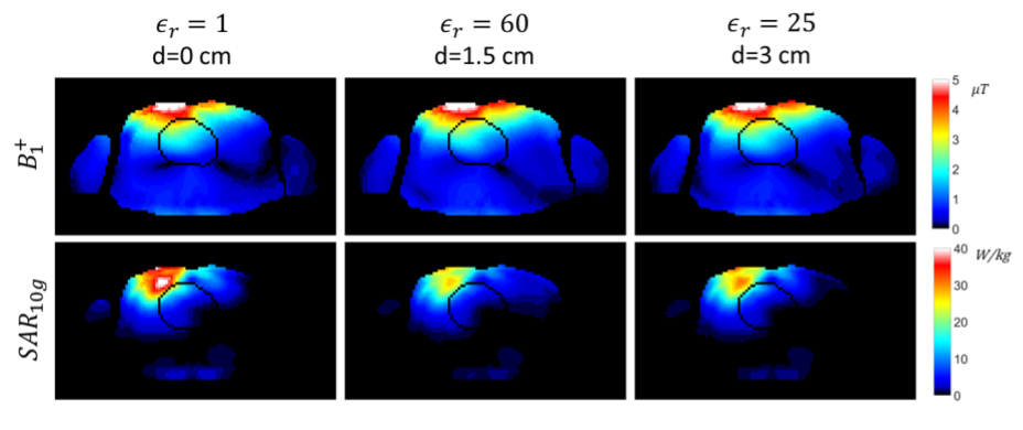
Figure 4. For the three configurations, no pads (left), 1.5 cm thick pad (middle), 3 cm thick pad (right), comparisons of the B1+ field distributions (top row), and the 10g average SAR profile (bottom row) .
DOI: https://doi.org/10.58530/2023/4254