4253
A screen-printed and electroplated 4-channel receiver array coil for veterinary imaging1Hawkcell, Marcy l'étoile, France, 2Université de Lyon, INSA Lyon, Université Claude Bernard Lyon 1, Ecole Centrale de Lyon, CNRS, Ampère UMR5005, Villeurbanne, France
Synopsis
Keywords: RF Arrays & Systems, RF Arrays & Systems, Animals
In this work, we present a 4-channel receiver array entirely dedicated to veterinary imaging. For this purpose, we have fabricated an array coil on a flexible substrate using silver-ink screen printed process and copper electroplating. This flexible and conformable array coil has the potential to improve veterinary diagnosis with small form-fitting elements that allow a better signal to noise ratio performance.Introduction
Magnetic resonance imaging is one of the most widely used imaging techniques in the world. In order to increase image quality and diagnosis accuracy, several techniques have been developed and improved over time in magnetic resonance such as magnetic field increasing1, development of flexible phased array coils2 and finally deep learning techniques for processing imaging. However, in veterinary clinics, imaging techniques still are obsolete with reconditioned machines and, more recently, array coils at very low field. At high field, the coils used are the human coils. These coils lack of adaptability to satisfy the clinical veterinary constraints, resulting in poor image quality and a diagnosis that may be compromised. In the context of cats and small dogs MRI (under 10kg) , the size of each element of the coil array is oversized and result in suboptimal signal to noise ratio (SNR) performance in the region of interest. Moreover, a positioning device require for the animal positioning is not available and results in poor quality images and an animal positioning different from standard anatomical conditions. In this work, we present a 4-element array coils with small channels which allow a better SNR performance at the region of interest, i.e. here the spine, while preserving the animal in a comfortable and correct position for diagnosis.Materials and methods
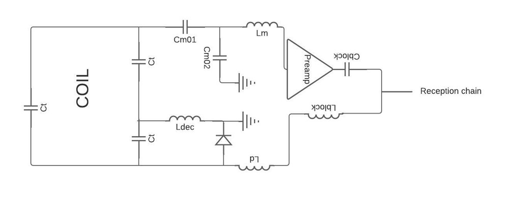
A 4-channel array coil was manufactured using 500µm polycarbonate substrate. A layer of 10 µm of silver ink Dupont ME603 was deposited using screen-printed process. After cured at 120°C for 20min, a copper thickness was deposited on the array coil using electroplating as presented in Gerges et al [3].The MR-coils geometry was a square with 40mm length and 3mm width and they are separated by a distance of 4mm between each channel. The inductive decoupling was used for the decoupling between elements when used in a phased array coil. Fig 01 shows the circuit diagram of a single element.
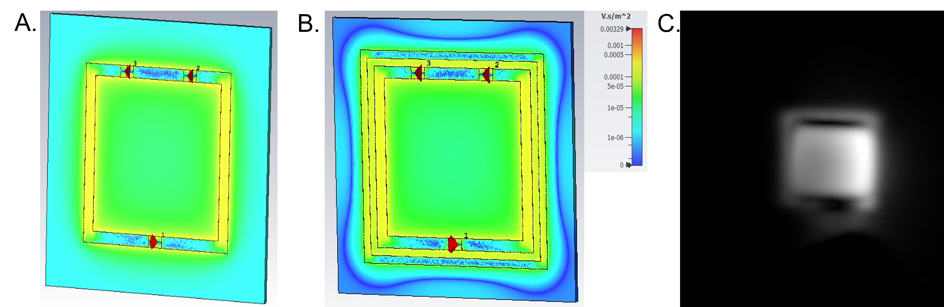
3D simulations of an isolated element of the array were performed using CST Microwave Studio to investigate the effect of the decoupling ring on the B1- map.
A FR4 substrate was used to contain the active detuning circuit, the matching and preamplifier decoupling circuit as well as the preamplifier. Active detuning was implemented on each element of the coil array to allow using the body coil of the MR scanner for transmission. The Wang et al[4] methods was used to implement the preamplifier decoupling.
Each element was tested independently and sequentially on a dedicated RF bench. Measurements of S-parameters, Q-factors, active detuning and preamplifier decoupling were performed with a Vector Network Analyze (R&S ZNL3). The loaded and unloaded quality factor of the coil were measured using the single loop method5 and a cylindrical phantom filled with a solution of CuSO4. The active detuning was tested by measuring with the double probe method6 the difference on S11. The preamplifier decoupling level was evaluated using double loop methods by comparing the S21 value at f =63.8MHz when the coil was connected to a low noise preamplifier and then a 50Ω charge (preamplifier noise match impedance).
The MRI experiments are performed using a MR scanner 1.5T. A 3D gradient echo was performed (TE/TR = 5.6/2.56 , 12° flip angle, 256x256 matrix , 1mm slice thickness) using a homogeneous cylindrical phantom.
Results
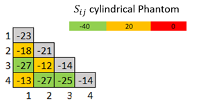
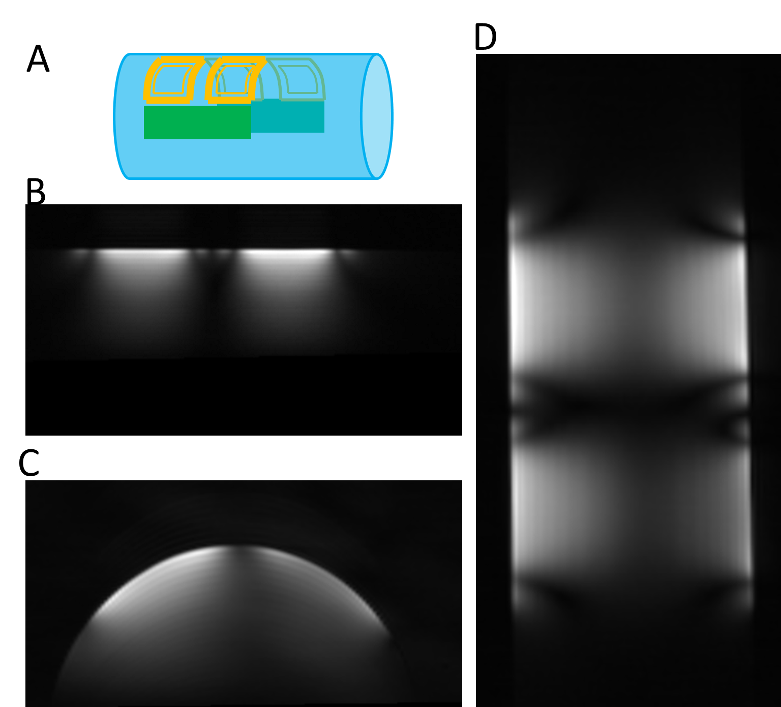
Figure 02 shows a picture of the fabricated MR array coil. All the coils are tuned at the Larmor frequency and match to a level bellows -14dB. Mutual decoupling was measured at least below -18dB for all elements. The preamplifier decoupling presented at least a 15dB of isolation. The active detuning generated 40dB of isolation for all the elements. Figure 03 shows the S matrix of the coil array.Figure 04 A,B and C shows the images acquired with a cylindrical phantom in the sagittal, axial and coronal planes respectively.
Figure 05 A and B show respectively the simulated B1- map of one element of the array with and without the decoupling ring. The figure 03 C shows the image obtained with one element. The magnetic field cancelation observed in simulations are confirmed with the presence of imaging artefacts.
Discussions
In this work we presented the design, building and testing of a 4-channel phased array coil dedicated to veterinary MRI. Nevertheless this preliminary results showed that the manufacturing process and the decoupling scheme need to be still optimized.First, adhesion stress of the ink to the polycarbonate film was noticed. As a consequence, the adhesion of the copper was damaged, causing copper cracking and conductivity problems.
The packaging of the tracks and electronics could improve the robustness of the coil array.
Second, the decoupling ring is used because it does not depend on the geometry or arrangement of the elements and does not needs of additional components. However, magnetic field cancelation due to decoupling ring observed in simulation were also verified in imaging. An optimization of the inductive ring decoupling will be carried out.
In vivo MRI tests with dogs and cats will be carried out in the future.
In conclusion, this flexible and conformable array coil could improve veterinary diagnosis with small form-fitting elements that allow a better signal to noise ratio performance.
Acknowledgements
No acknowledgement found.References
[1] Wiesinger, F., Van de Moortele, P.-F., Adriany, G., De Zanche, N., Ugurbil, K. and Pruessmann, K.P. (2006), Potential and feasibility of parallel MRI at high field. NMR Biomed., 19: 368-378. https://doi.org/10.1002/nbm.1050
[2] P. B. Roemer, W. A. Edelstein, C. E. Hayes, S. P. Souza, et O. M. Mueller, « The NMR phased array », Magn Reson Med, vol. 16, nᵒ 2, p. 192‑225, nov. 1990, doi: 10.1002/mrm.1910160203.
[3] T. Gerges, V. Semet, P. Lombard, S. Gaillard, M. Cabrera, et S. A. Lambert, « 3D Plastronics for Smartly Integrated Magnetic Resonance Imaging Coils », Front. Phys., vol. 8, p. 240, juill. 2020, doi: 10.3389/fphy.2020.00240.
[4] W. Wang, V. Zhurbenko, J. D. Sánchez‐Heredia, et J. H. Ardenkjær‐Larsen, « Three‐element matching networks for receive‐only MRI coil decoupling », Magn. Reson. Med., vol. 85, nᵒ 1, p. 544‑550, janv. 2021, doi: 10.1002/mrm.28416.
[5] J.-C. Ginefri, E. Durand, et L. Darrasse, « Quick measurement of nuclear magnetic resonance coil sensitivity with a single-loop probe », Review of Scientific Instruments, vol. 70, nᵒ 12, p. 4730‑4731, déc. 1999, doi: 10.1063/1.1150142.
[6]Darrasse L, Kassab G. Quick measurement of NMR-coil sensitivity with a dual-loop probe. Rev Sci Instrum. 1993; 64: 1841–1844.
Figures