4252
8kw non-magnetic RF power amplifier with four-way combiner for 5T MRI1Paul C. Lauterbur Imaging Research Center, Shenzhen Institutes of Advanced Technology, Chinese Academy of Sciences, Shenzhen, China, 2Key Laboratory for Magnetic Resonance and Multimodality Imaging of Guangdong Province, Shenzhen, China, 3Chongoing Universit of Technology, Chongqing, China, 4Department of Biomedical Engineering, State University of New York at Buffalo, Buffalo, NY, United States
Synopsis
Keywords: RF Arrays & Systems, RF Arrays & Systems, RF power amplifier
Ultra-high-field magnetic resonance requires higher power capability and transmission efficiency. An 8 kW non-magnetic RF power amplifier with four-way combiner for 5T MRI is presented. The whole module adopts non-magnetization design to improve transmission efficiency, and the power of four MOSFETs is combined by a combiner with adjustable balance to meet the output power of 8 kW.Introduction
Ultra-high-field(UHF) MRI systems have become a focus in clinical and scientific research, and have been shown to play an important role in improving sensitivity and spatial resolution [1,2]. However,UHF whole body imaging requires radio frequency power amplifier (RFPA) to have higher power capability as field becomes stronger[3]. At the same time, transmitting high-power RF signals from the equipment room to RF coils that located in the scanning room will cause more power loss [4]. This work designed an 8 kW non-magnetic RFPA for 5T MRI. The non-magnetic structure design allows the RFPA to be placed in the scanning room to reduce transmission loss, and the power stage is amplified by four MOSFETs(Metal Oxide Semiconductor Field Effect Transistor) so as to obtain an output power of 8 kW (69 dBm).In order to ensure the combine efficiency of each MOSFET,a four-way combiner with adjustable balance is adopted.Methods
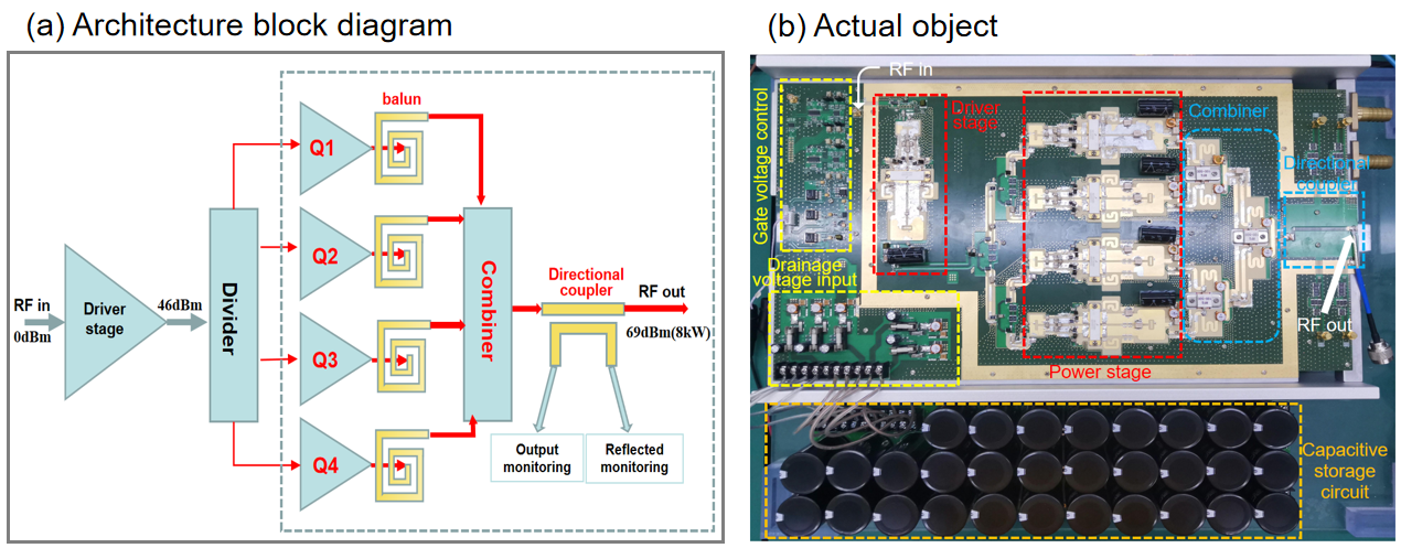
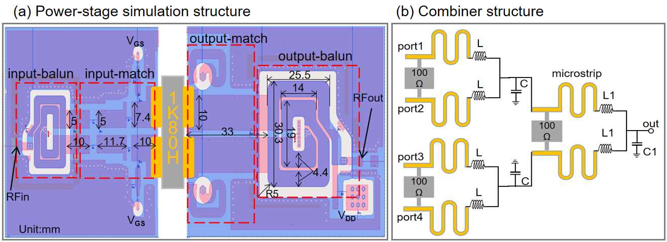
High-power output and non-magnetic structure are the key factors in this work. The structure of the RFPA as shown in Figure 1(a),the low-power RF signal is amplified by the driver amplification circuit to reach the driving level of the power stage amplifier , in order to achieve the gain linearity of the whole machine, the 1dB compression point(P1dB) of the driver stage is required to be greater than 48 dBm. And then the energy outputs to the four power amplification paths averagely through two-stage Wilkinson power divider.LDMOS MRFX1K80H(NXP, The Netherlands) is selected as the key power device of power stage and driver stage.The structure of single power stage is shown in Figure 2(a), a 4:1 non-magnetic planar balun was used as the impedance converter, performance of the planar balun was simulated in Advanced Design System(ADS) with the model of MRFX1K80H. In addition, the microstrip directional coupler replaces the traditional magnetic ring as the monitor of forward and reflected power. To achieve the output power of 8 kW, the power stage is amplified with four parallel MOSFETs.
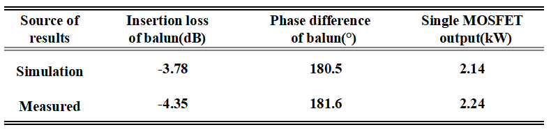
The inconsistency of the amplitude and phase of each port will increase insertion loss, so we use a four-way power combiner with adjustable balance, as shown in Figure 2(b), replacing the original inductor with a microstrip and a small inductor that can adjust the inductor L, capacitor C to keep the amplitude error and phase error of each port unobviously. Since the combiner is not an ideal -3 dB power synthesizer, there will be a insertion loss, to compensate for the attenuation of it, the output power of single MOSFET is required to be greater than 2.2 kW.
Results
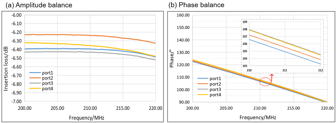
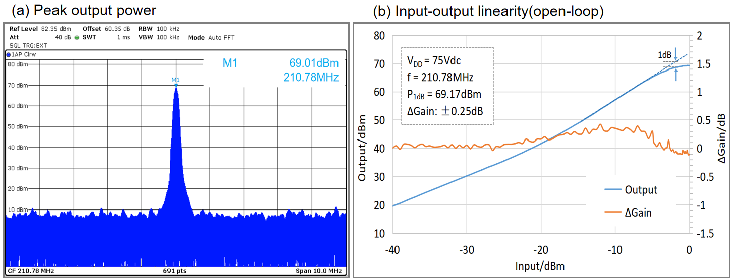
The results in Table.1 shown that use a planar non-magnetic balun structure also meets the design specification, and contacted with matching circuits single MOSFET can output power of 2.24 kW.Through the combiner with adjustable balance, the amplitude and phase of each port is unanimously, as shown in Figure 3, within the sweep bandwidth of 20 MHz, the amplitude error of each port is less than 0.2 dB, the phase error is within 2°.After combineing the power of four MOSFETs, the RFPA can output a saturated peak power of 8.5 kW(69.3 dBm) and the P1dB at 69.17 dBm with the dynamic range of 40 dB, in the open-loop test, the gain fluctuation is less than 0.5dB(Figure 4). This work has shown that the RFPA based on non-magnetic planar balun and four-way combiner has low insertion loss and high output power.Furthermore, the input-output relationship has a steady linearity.
Discussion
Compared with the previous non-magnetic power amplifier [05], this 8 kW RFPA has higher output power, while contrasted with the existing high-power amplifier [03], this non-magnetic power amplifier can be placed in the scanning room with lower transmission loss. The further work is to design the feedback control loop for better output stability and safety, and expand the number of amplifier channels to excite multiple RF coils simultaneously.Conclusion
In this work, an 8 kW non-magnetic RF power amplifier is designed for 5T MRI, the results shown that it has high output power with four-way adjustable combiner and low transmission loss by non-magnetic design.Acknowledgements
This work is supported by National Key Research and Development Program of China, 2021YFE0204400; the Strategic Priority Research Program of Chinese Academy of Sciences, XDB25000000; National Natural Science Foundation of China, U22A20344; Youth Innovation Promotion Association of CAS No. Y2021098; Key Laboratory Project of Guangdong Province, 2020B1212060051; Shenzhen city grant, RCYX20200714114735123.References
[1] Orzada S, Solbach K, Gratz M, et al. A 32-channel parallel transmit system add-on for 7T MRI[J]. PLoS One. 2019;14(9):e0222452.
[2] Vachha B, Huang S Y. MRI with ultrahigh field strength and high-performance gradients: challenges and opportunities for clinical neuroimaging at 7 T and beyond[J]. European Radiology Experimental, 2021, 5(1): 1-18.
[3] Chen JF, Li Y, Zhang H, et al. High power RF amplifier for UHF MRI with configurable number of channels. ISMRM 2021 Abstract 1585.
[4] Vaughan JT, Myer D. RF Coil element mounted power amplifiers. In Proceedings of the 19th Annual Meeting of ISMRM, Montreal, Canada, 2011. Abstract 1851.
[5] Luo J, Liu S, Chen J, et al. A 2kW non-magnetic RF power amplifier with negative feedback for 5T MRI proton imaging.ISMRM 2022 Abstract 1585.
Figures