4251
MATCHING CIRCUIT CO-SIMULATION FOR MR RADIOFREQUENCY COIL SYSTEM OPTIMIZATION
Amer Ajanovic1, Stephen Ogier2,3, Raphael Tomi-Tricot1,4,5, Joseph V Hajnal1,4, and Shaihan Malik1,4
1Biomedical Engineering Department, School of Biomedical Engineering and Imaging Sciences, King's College London, LONDON, United Kingdom, 2National Institute of Standards and Technology, Boulder, CO, United States, 3Department of Physics, University of Colorado, Boulder, CO, United States, 4London Collaborative Ultra high field System (LoCUS), London, United Kingdom, 5MR Research Collaborations, SIEMENS Healthcare Limited, Frimley, United Kingdom
1Biomedical Engineering Department, School of Biomedical Engineering and Imaging Sciences, King's College London, LONDON, United Kingdom, 2National Institute of Standards and Technology, Boulder, CO, United States, 3Department of Physics, University of Colorado, Boulder, CO, United States, 4London Collaborative Ultra high field System (LoCUS), London, United Kingdom, 5MR Research Collaborations, SIEMENS Healthcare Limited, Frimley, United Kingdom
Synopsis
Keywords: RF Arrays & Systems, Simulations, RF Pulse Design and Fields, parallel transmit coils
We present a full closed form solution focusing on S-parameters to achieve tuning and matching of the coils by extending the circuit co-simulation (CCS) by enabling introduction of arbitrary matching networks into the CCS without requiring full RF simulation of the network. We validate the method against CCS and demonstrate its applicability to evaluate full-field solutions for 5 different coil model using MARIE.Introduction
MRI radiofrequency (RF) coils’ passive components often require full EM simulation, even those in electrically small networks that have little impact on current or field distributions. Circuit co-simulation (CCS) was developed to allow the lumped element components of coils to be varied and optimized without having to re-run a full simulation each time[1]. CCS can be used to tune the coil to the right frequency very quickly[2]; however, it does not account for power losses due to mismatch between the excitation network and the coil. The RF engineering community has implemented methods to allow the passive electronic elements' placement at ports and obtain full EM solution. A method using circuit-spatial optimization has been proposed[4] to calculate S-parameters coupled with spatial field optimization in full simulation of 16-element transceiver array at 7T. Here we present a full closed form solution focusing solely on S-parameters to achieve tuning and matching. Starting with the original CCS implementation in MATLAB[2], we extend it by introducing Matching Circuit Co-Simulation (MCCS) to enable introduction of arbitrary matching networks into the CCS without requiring full RF simulation of the network.Theory
Introducing a capacitive and inductive T-network between the excitation and the coil (Fig.1) allows us to implement a closed form relation of the physical S-parameters. There are $$$p$$$ driven ports to the coil and $$$l$$$ lumped element ports. There are $$$p$$$ matching networks, one for each driven port, and $$$l$$$ passive components, one for each lumped element port.Matching Networks. $$$M$$$ is a $$$2p \times 2p$$$ matrix of the matching network S-parameters. They are organized into four blocks, each $$$pxp$$$:
$$$\bf M_{DD}$$$ is a $$$p \times p$$$ matrix of voltage scattered from the driven side of the matching networks by voltage incident on it.
$$$\bf M_{DP}$$$ is a $$$p \times p$$$ matrix of voltage scattered from the driven side of the matching networks by voltage incident on the coil side of the matching networks.
$$$\bf M_{PD}$$$ is a $$$p \times p$$$ matrix of voltage scattered from the coil side of the matching networks by voltage incident on the driven side of the matching networks.
$$$\bf M_{PP}$$$ is a $$$p \times p$$$ matrix of voltage scattered from the coil side of the matching networks by voltage incident on it. When each matching network is an independent 2-port network, each block is a diagonal matrix of $$$p$$$ S-parameters.
Coil. $$$S$$$ is a $$$(p+l) \times (p+l)$$$ matrix of the coil S-parameters. It is likewise organized into four blocks, but these are of different sizes. Additionally, the four-component matrices are not diagonal.
$$$\bf S_{PP}$$$ is a $$$p \times p$$$ matrix of voltage scattered from the driven coil ports by voltage incident on them.
$$$\bf S_{PL}$$$ is a $$$p \times l$$$ matrix of voltage scattered from the excited coil ports by voltage incident on the lumped element coil ports.
$$$\bf S_{LP}$$$ is a $$$l \times p$$$ matrix of voltage scattered from the lumped element coil ports by voltage incident on the driven coil ports.
$$$\bf S_{LL}$$$ is a $$$l \times l$$$is a matrix of voltage scattered from the lumped element coil ports by voltage incident on them.
Lumped Elements. $$$\bf \Sigma$$$ is an $$$l \times l$$$ matrix of lumped element S-parameters. If the ports are not interconnected, the matrix is diagonal.
Solution. The derivations are provided in Fig.2 using Matrix Signal Flow Graph approach. We first verify the result from Beqiri[2]; $$$\bf S^{CCS}$$$ is the S-matrix of the coil ports without the matching network:
$$\bf S^{CCS}=S_{PP}+S_{PL} \Sigma (I-S_{LL} \Sigma)^{-1}S_{LP}$$
When the matching network is added, the following expression for the S-matrix of the matched coil, $$$\bf S^{MCCS}$$$, is obtained:
$$\bf S^{MCCS}=M_{DD}+M_{DP}S^{CCS}(I-M_{PP}S^{CCS})^{-1}M_{PD}$$
Methods
The MCCS implementation was first validated against CCS by open-circuiting the shunt capacitor (Csh in Fig.1) and short-circuiting the other 2 capacitors in the matching network. To use it to tune-and-match the coils, a cost function consisting of S-parameters was subject to linear constraints and minimized by optimizing matching network elements, similarly to Li[4] in MATLAB. MCCS was further combined with MARIE[3] to demonstrate applicability to full simulation of 4 realistic coil models coupled with human body models (here Duke[5]).Results and Discussion
Fig.3 shows the error is insignificant when using MCCS to estimate an equivalent scenario with CCS. Fig.3 also demonstrates the S-parameters curve for matching network capacitances' variation for a 4-channel-coil, showing well matched coil at return losses up to -60dB. The optimized circuit components were consistent over the 5 coils examined, producing on-diagonal S-parameters <-25dB and off-diagonal ones <-15dB, as shown in Fig.4. Therefore, all coils are well tune-and-matched. Fig.5 shows an example usage of MCCS to combine the fields per each excited channel of the 2 coils (2-channel-shielded-birdcage-coil and 8-channel-pTx-coil) computed via MARIE.The proposed method can incorporate decoupling transformers/coupled inductors, shared capacitors, and more complicated decoupling networks without having to perform full-wave simulation of the entire circuit structure. These more complicated networks can be incorporated into $$$\bf \Sigma$$$, which will no longer be diagonal. Accomplishing this can be extended by optimizing off-diagonal S-parameters to achieve better decoupling.
Conclusion
The proposed extension to co-simulation method efficiently achieves coil tuning-and-matching and combined with MARIE accurately produces full EM simulation of the coils.Acknowledgements
This work is funded by the King’s College London & Imperial College London EPSRC Centre for Doctoral Training in Medical Imaging (EP/L015226/1). This work was supported by the core funding from the Wellcome/EPSRC Centre for Medical Engineering [WT203148/Z/16/Z] and by the National Institute for Health Research (NIHR) Biomedical Research Centre based at Guy’s and St Thomas’ NHS Foundation Trust and King’s College London and/or the NIHR Clinical Research Facility. The views expressed are those of the author(s) and not necessarily those of the NHS, the NIHR or the Department of Health and Social Care.References
[1] M Kozlov, JMR Vol 200, 147 (2009);
[2] A Beqiri, MRM Vol 74, 1423 (2015),
[3] JF Villena, IEEE BME Vol 63, 2250 (2016),
[4] X Li, MRM Vol 85, 3463 (2021).
[5] Christ PMB 2009.
Figures
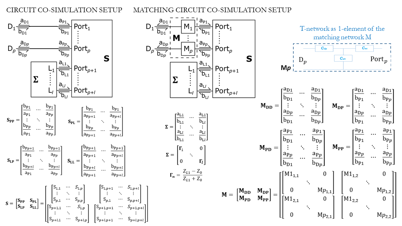
Figure 1: Diagram of RF coil and passive
networks with main S-parameter matrices.
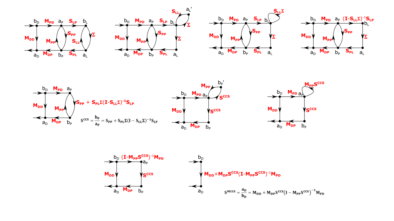
Figure 2: Derivation of the matching
circuit co-simulation using circuit matrix signal flow graphs.
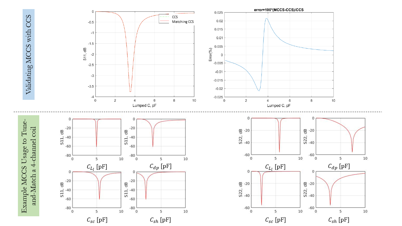
Figure 3: Top: MCCS validation with CCS. Bottom:S11 and S22 parameters plots with respect to matching network
capacitances for the 1st and 2nd driving ports of the 4-channel pTx coil at
their respective resonance conditions obtained via MCCS. Notice
the global minimum is at around -60 dB return loss.
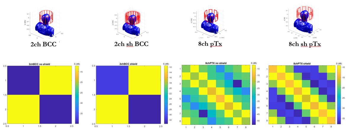
Figure 4: The evaluated S-parameters
for 4 coils (left-right: 2-channel birdcage, 2-channel shielded birdcage,
8-channel pTx, 8-channel shielded pTx coil) evaluated by optimizing inductive
and capacitive matching network elements.
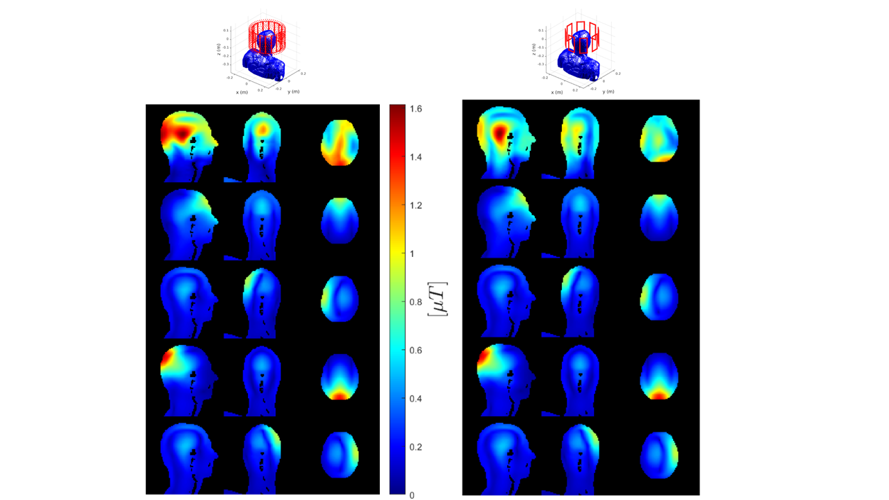
Figure 5: Example usage
of MCCS to combine fields per channel evaluated with MARIE. Left: 2-channel
shielded birdcage coil B1+, right: 8-channel pTx coil B1+, obtained using
MARIE+MCCS. Top row: combined CP mode B1+ using the B1+ per channel, for
selected 4 channels (2nd-3rd row on the left: B1+ per the 2 driven channels of
the 2-channel shielded birdcage coil; 3rd-4th row: 2 non-driven channel B1+
maps; 2nd-4th row on the right: selected 4 driven channel B1+ maps from the
total of 8 driven channel B1+s).
DOI: https://doi.org/10.58530/2023/4251