4249
Impacts of Longitudinal Coil Encoding on Simultaneous Multi-Slice (SMS) Head MRI1Division of Translational Imaging, Department of Psychiatry, Columbia University, New York, NY, United States, 2MRI Research Center, New York State Psychiatric Institute, New York, NY, United States, 3Columbia MR Research Center, Columbia University, New York, NY, United States
Synopsis
Keywords: RF Arrays & Systems, RF Arrays & Systems
Coil encoding in the longitudinal direction (z-direction) plays an important role in SMS MRI quality. Although many head coil arrays have been reported, systematic research on impacts of coil encoding in the longitudinal direction on SMS imaging remains insufficient. We present a comparison study of coil encoding for head arrays. Our experimental results showed that, to achieve quality images, the mulitband factor should be equal to or less than the number of coil rows. In extreme cases, the mulitband factor should not exceed 1.5 times the number of coil rows.Introduction
The rapidly increasing applications of RF coil arrays [1] with a growing number of coil elements have made simultaneous multi-slice (SMS) MRI more and more demanding and practical [2,3]. Coil encoding in the longitudinal direction (z-direction) plays an important role in SMS imaging quality [4]. For head MRI, however, the layouts of coil elements are dramatically restricted by the dimensions of coil formers and the number of coil elements, leading to extreme complexities in the design and implementation of the coil arrays. Although many head coil arrays have been reported [e.g. 5-8], systematic research on impacts of coil encoding in the longitudinal direction on SMS imaging remains insufficient. We present a comparison study of coil encoding for head arrays.Materials and Methods
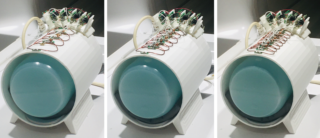
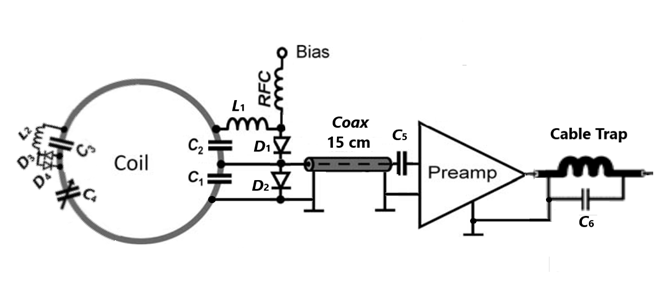
To avert interference among a huge number of coil elements, we simplified our research model to three arrays with 4, 6 and 8 coil loops respectively. The loops were placed in the longitudinal direction on the top of 3D-printed cylindrical formers having a length of 280mm and an inner/outer diameter of 190/196 mm. The length of all arrays was set to 220mm to simulate most commercially available head arrays. The rear part of each former was used to house preamplifier modules (Figure 1).The coil loops were elliptical and have a major axis of 75mm in azimuthal direction. The minor axes of the loops in the longitudinal direction, however, were adjusted to 35, 45 and 65 mm for the arrays with 4, 6 and 8 elements respectively to fit for the fixed length of 220 mm. The loops were made of 14-AWG enameled copper wires. Adjacent loops were overlapped by a critical distance (~ 25% of the minor axes) for primary decoupling. Each loop was connected to a low input impedance preamplifier for preamplifier-based decoupling and actively detuned by bias pulses with a trap circuit formed by C2, D1, and L1 and passively detuned with C3, D3, D4 and L2 during RF transmission. A cable trap was built at the output of the preamplifier to choke surface currents (Figure 2).
Axial images were acquired from a cylindrical phantom (ScanMed LLC, Omaha, NE, USA) having a diameter of 160mm and a length of 250mm in a 3T MRI scanner (GE Premier) using a 2D EPI pulse sequence (TR=2800ms, TE=30ms, Flip Angle=90, FOV = 200x200 mm2, Slice Thickness=2.5mm, NEX=1, Bandwidth=250kHz, Matrix=80x80, Number of Slices = 100). The imaging experiment was repeated for each coil array without SMS and with SMS at multiband factors (MB, the number of simultaneously acquired slices) of 2, 4, 6 and 8 respectively for comparison.
Results and Discussion
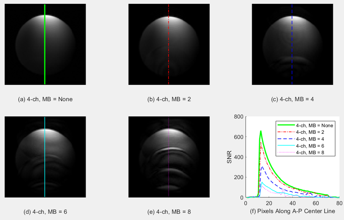
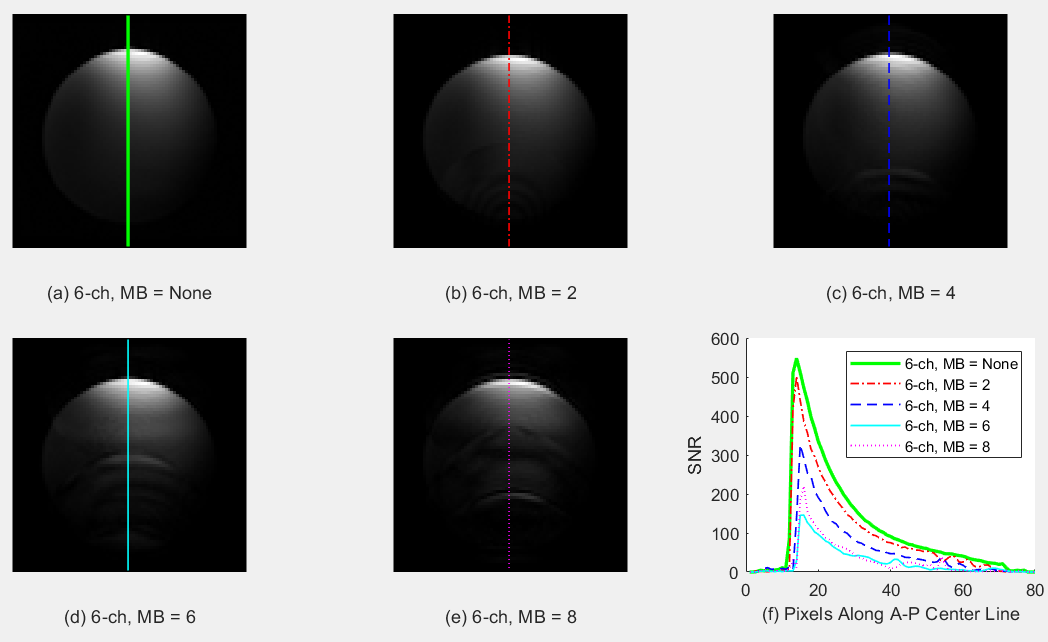
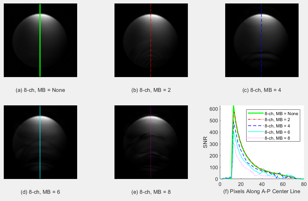
The experimental results showed that the arrays with more coil loops were significantly superior to the arrays with less loops. Specifically, without SMS, the images of all arrays were smooth (Figure 3a, 4a, 5a) with SNR profiles peaking at 550-650 in the top periphery (bold green, Figure 3f, 4f, 5f). With SMS, at MB = 2, the images of all arrays remained smooth (Figure 3b,4b,5b) though the SNR of the 4-ch array decreased by about 15% and the SNRs of the 6-ch and 8-ch arrays decreased by 5-8% (dash-dotted red, Figure 3f, 4f, 5f). At MB = 4, the image of the 4-ch array became slightly deformed at the bottom while the images of the 6-ch and 8-ch arrays remained relatively smooth (Figure 3c,4c,5c). The SNR of the 4-ch array degenerated by about 50% while those of the 6-ch and 8-ch arrays degenerated by about 35% and 25% respectively (dashed blue, Figure 3f, 4f, 5f). At MB = 6, the image of the 4-ch array was further deformed, the image of the 6-ch array also was slightly deformed while the image of the 8-ch array remained relatively smooth (Figure 3d,4d,5d). The SNRs of the 4-ch, 6-ch and 8-ch arrays dropped by about 75%, 60% and 35% respectively (solid cyan, Figure 3f, 4f, 5f). At MB = 8, the image of the 4-ch array was severely wave-deformed, the image of the 6-ch array was also wave-deformed, the image of the 8-ch array, however, remained acceptable though it was slightly deformed as well (Figure 3e,4e,5e). Moreover, the SNRs of the 4-ch, 6ch and 8-ch decreased by about 85%, 70% and 50% respectively, indicating the image of 4-ch array was completely unusable, the image of the 6-ch was somewhat acceptable and the image of the 8-ch remained usable (dotted magenta, Figure 3f,4f,5f).Overall, when the multiband factor was approximately equal to the number of the coil elements, the images started to show deformation with SNRs degenerated by about 50%. When the multiband factor increased to twice the number of coil elements, the images were severely deformed and completely unusable with SNRs degenerated by up to 85%.
Conclusions
Coil encoding is crucial for SMS imaging. To achieve quality images, the multiband factor should be equal to or less than the number of coil rows in the longitudinal direction. In extreme cases, the multiband factor should not exceed 1.5 times the number of coil rows. In future work, we will investigate coil encoding with 32-64 coil elements which are very common in clinical settings.Acknowledgements
No acknowledgement found.References
1. Roemer PB, Edelstein WA, Hayes CE, Souza SP, Mueller OM. The NMR phased array. Magn Reson Med. 16:192-25(1990).
2. Breuer FA, Blaimer M, Heidemann RM, Mueller MF, Griswold MA, Jakob PM. Controlled aliasing in parallel imaging results in higher acceleration (CAIPIRINHA) for multi‐slice imaging. Magn Reson Med. 53:684–691(2005)
3. Markus Barth, Felix Breuer, Peter J Koopmans, David G Norris, Benedikt A Poser, Simultaneous multislice (SMS) imaging techniques, Magn Reson Med. 75(1):63-81(2016).
4. David J. Larkman, Joseph V. Hajnal, Amy H. Herlihy, Glyn A. Coutts, Ian R. Young, and Gosta Ehnholm, Use of Multicoil Arrays for Separation of Signal from Multiple Slices Simultaneously Excited, Journal of Magnetic Resonance Imaging 13:313–317 (2001).
5. G C Wiggins, C Triantafyllou, A Potthast, A Reykowski, M Nittka, L L Wald. 32-Channel 3 Tesla Receive-Only Phased-Array Head Coil with Soccer-Ball Element Geometry. Magnetic Resonance in Medicine 56:216–223 (2006).
6. Kamil Uğurbil, et al. Brain imaging with improved acceleration and SNR at 7 Tesla obtained with 64-channel receive array, Magn Reson Med. 82:495–509 (2019). 7. Bei Zhang, Alan C. Seifert, Joo-won Kim, Joseph Borrello, and Junqian Xu.
7. Tesla 22-Channel Wrap-Around Coil Array for Cervical Spinal Cord and Brainstem Imaging. Magnetic Resonance in Medicine 78:1623–1634 (2017).
8. Yunsuo Duan, Feng Liu, Rachel Marsh, Matthew Riddle, Gaurav H. Patel, John Gray, Alayar Kangarlu, Lawrence S. Kegeles, and John T. Vaughan Jr.. A 32-Ch Over-Overlapped Semi-Flexible RF Head Coil Array with Improved Deep Brain SNR. ISMRM Annual Meeting, 2022
Figures