4248
Proof of concept for auto-resonant structure to increase the field of view of surface coils1Universite Paris-Saclay, ORSAY, France, Metropolitan, 2Université Paris-Saclay, CEA, CNRS, Inserm, BioMaps, Orsay, France, 3Université Paris-Saclay, CEA, CNRS, BAOBAB, NeuroSpin, Gif-sur-Yvette, France, 4GEPI - Observatoire de Paris (CNRS 8111), Université PSL, Paris, France, 5Université Paris-Saclay, BioMaps, ORSAY, France
Synopsis
Keywords: Non-Array RF Coils, Antennas & Waveguides, Non-Array RF Coils, Antennas & Waveguides, Multi Loop Transmission Line Resonator
To improve the performances of High Temperature Superconducting surface coils, it is essential to enlarge their field of view while keeping the sample-induced noise low. New multi-loop designs could help meeting this challenge. In this work, we present a preliminary study on a copper coil. We first introduce the design, electromagnetic simulations, realization of a multi-loop transmission line resonator copper coil and experimental characterizations. Signal to Noise Ratio-maps of the coil are then acquired in a 3T field.Purpose
To avoid discrete components, High Temperature Superconducting (HTS) surface radio frequency coils implied transmission design approach (1), i.e. two twin spirals etched on opposite sides of a thin dielectric substrate. Their use in MRI is only relevant if the coil is the dominant source of noise. This condition limits the diameter of the coils, leading to a limited field of view (FOV) which reduces their applications.The use of arrays have been envisaged as a strategy to increase the FOV of HTS coils, but the remaining magnetic coupling between elements makes them inoperable (2). Multi Loop Coils (MLC) (3) also minimize the sample-induced noise and, most of all, their structure naturally prevents magnetic coupling between the elements.
Until now, MLC have been tuned with discrete capacitors. To avoid the soldering of discrete elements on the superconducting material, the design have to be modified to integrate a distributed capacity and become self-resonant.
A proof of concept of a multi-loop transmission line resonator on a copper coil (MLTLR) is presented. After presenting the results of electromagnetic simulations, MLTLR is fabricated, electrically characterized. Signal to Noise Ratio (SNR)-maps obtained with the MLTLR were then acquired.
Methods
The symmetry of an initial 19-loop design have been increased to allow the overlap of two structures on opposite sides of a 1.6 mm thick epoxy substrate. Two opposite gaps have been added on the conductors on each side (one gap per side) to create a Transmission Line Resonator (TLR). The diameter of the loops is 8.4 mm, the copper 1.25 mm wide and 35 µm thick. The outer diameter of the coil is 50 mm. The design represented on figure 1 have been simulated on a finite element method solver (HFSS Ansys) and then manufactured in the lab. The size of the coil is chosen so that it resonates near but above 127.73 MHz. The coil was finely tuned inside the MRI magnet, in presence of a cylindrical sample of water, by adding a dielectric pad. The built-in 3DFastSPGR sequence of a 3.0 Tesla GE Signa PET/MRI scanner was performed to obtain SNR-maps, with a head coil array coupled with the investigated MLC for reception. The sequence parameters are : repetition time TR = 14.027 s ; echo time TE = 3.308 s ; image size : 60 × 256 × 256 voxels ; resolution : 1 mm × 0.43 mm × 0.43 mm.Results
The electromagnetic simulation shows a resonance at 142 MHz. Experimentally, the coil resonates at135.4 MHz. The unloaded and loaded Q-factor are respectively of 42 and 41.
Figure 2 shows the multi loop structure and SNR-maps of the surface coil. It can be observed that the MLTLR produces a high but inhomogeneous B1 field near its surface. In the depth of the sample, the signal is more homogeneous.
Discussion
This preliminary work on a copper surface coil proves MLTLR can be designed to widen the FOV of surface coils. The good agreement of the simulations with the experimental results (the error on the resonance frequency is 5.2%) validates our simulation method. Considering the Q-factor unloaded and loaded, the coil noise dominates and a SNR gain of about 5,5 will be expected working with HTS material at 60K. Special care will be taken in the design of the RF coil to improve the homogeneity of B1 in its vicinity. It can be noted that the decoupling of HTS coils will be achieved through their non linear properties avoiding the use of an added decoupling element.Acknowledgements
The authors thank Mr. Javier Briatico (CNRS /Thales) and Thales Research & Technology. The authors are indebted to Mr Georges Willoquet, Mrs Rose-Marie Dubuisson and Mrs Angéline Nemeth for their assistance in this studyReferences
1. P. Gonord, S. Kan, A. Leroy-Willig, Magn. Reson. Med. 6 (1988) 353–358
2. Zhoujian Li, Luc Darrasse, and Jean-Christophe Ginefri. Preliminary investigation on shielding-ring based technique for miniature monolithic rf coil decoupling. Proc.ISMRM 2015, Toronto, Canada. (Poster, p.559)., 2015.
3. Roberta Frass Kriegl, Sajad Hosseinnezhadia, Marie Poirier-Quinot, Elmar Laistler, and JeanChristophe Ginefri. Multiloop radiofrequency coil elements for MRI: Theory, simulation and experimental investigation. Frontiers in Physics, jan 2020.
Figures
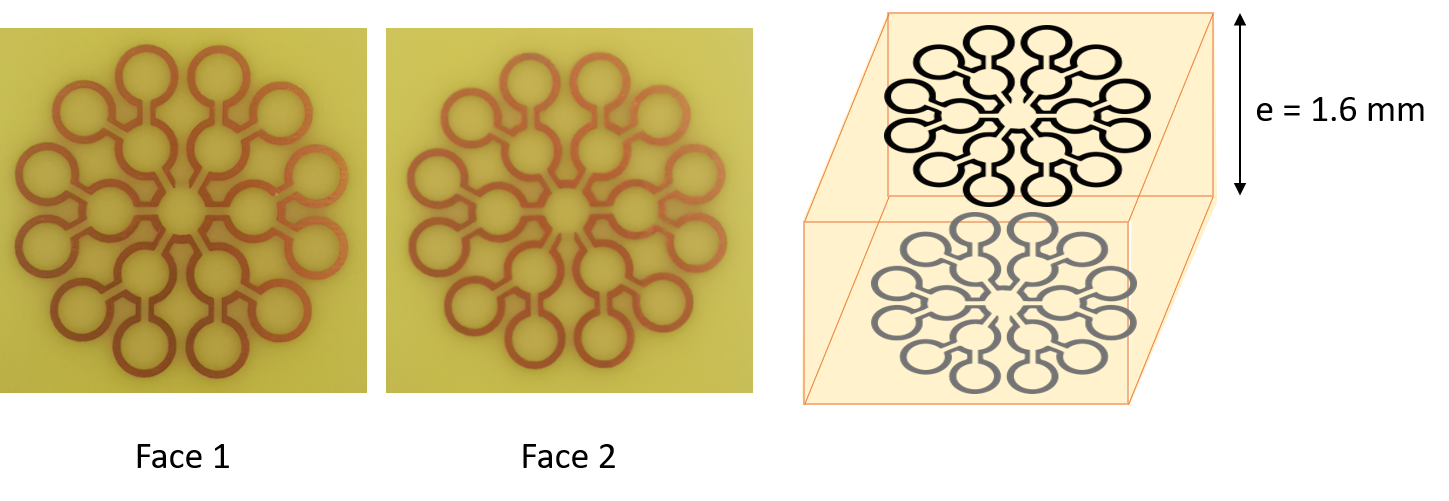
Pictures of the two faces and schematic representation of the investigated MLTLR. The thickness of the 1.6mm epoxy substrate have been exaggerated for more clarity. The opposite gaps are visible on the drawing. The diameter of the loops is 8.4 mm, the copper 1.25 mm wide and 35 µm thick. The outer diameter of the coil is 50 mm.
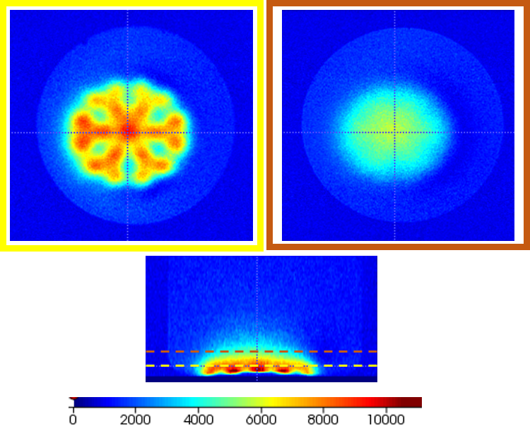
Coronal and axial slices of SNR-maps of the investigated copper MLTLR. The MLTLR has a high but inhomogeneous sensibility near its surface, which is not the case deeper in the sample.