4246
Disentangling coil coupling mechanisms through a Faraday equivalent model: application to the shielded-coaxial-cable (SCC) coil at 7T1Department of Electrical Engineering, Technical University of Eindhoven, Eindhoven, Netherlands
Synopsis
Keywords: RF Arrays & Systems, High-Field MRI, Coupling, SCC coils, Faraday's law of induction, SAR reduction
Minimizing coupling between coils constitutes a major challenge in the design of flexible arrays for UHF MRI. Recently, Shielded-coaxial-cable coils (SCC) were shown to be flexible and intrinsically highly decoupled: however, the decoupling mechanism of SCC remains unclear. In this work, we use an high frequency Faraday-equivalent model of the induced voltage to examine coupling between two SCCs in different geometrical configurations. We show that lower coupling in SCC derives from both lower magnitude of electric and magnetic fields as compared to a loop coil, and we discuss the implications in the design of coils for MRI.Introduction
Especially in the design of flexible arrays, a major challenge is minimizing coupling between coils. Shielded-Coaxial-Cables (SCC) provide flexibility, intrinsic decoupling characteristics, and straight-forward fabrication1,2, but their decoupling mechanism is still unclear. Understanding coupling of SCCs could enable the design of novel and more efficient coil elements. In this work, we derived an high frequency Faraday-equivalent model of the induced voltage and examined coupling between two SCCs in different configurations.Methods
Using the reciprocity theorem3 , the reaction concept4 , and the full set of Maxwell equations, we derived an expression for the coupled voltage of two coils:$$ (1) \; \; \; V_{21} = \oint_S ( \textbf{E}_{2}\times \textbf{H}_{1} ) \cdot d\textbf{S} + j\omega \left( \int_V \varepsilon \textbf{E}_2 \cdot \textbf{E}_1 dV + \int_V \mu \textbf{H}_2 \cdot \textbf{H}_1 dV \right) $$
where $$$V_{21}$$$ is the open-circuit voltage induced at the port of coil 2 when coil 1 is active–i.e. the coupled voltage - $$$\textbf{E}_{1}$$$ ($$$\textbf{H}_{1}$$$) is the electric (magnetic) field radiated by coil 1, when coil 1 is excited with 1A of current and coil 2 is open-circuited–and vice versa for $$$\textbf{E}_{2}$$$ and $$$\textbf{H}_{2}$$$-$$$V$$$ is a volume containing at least source 2, and the surface integral is extended over the contour of $$$V$$$, $$$S$$$.
Expression (1) generalizes Faraday’s law of induction, as it represents the voltage induced at the ports of a coil at any desired frequency and for any configuration. Faraday’s law of induction has been extensively used in MRI literature to model coupling in the low-frequency approximation5,6.
In expression (1), it is possible to recognize similar terms of electric coupling and magnetic coupling as defined in Hong7,8 , or Awai9-11 . The additional term accounts for electric and magnetic coupling contributions outside $$$V$$$. Note that the theory of Hong was used to explain the rationale in the design of Self-Decoupled-Coils12, and that electric coupling in Hong is defined the same as in Roemer5 .
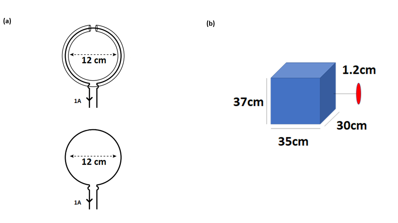
We apply expression (1) to the case of two-coil arrays, one of of SCCs and the other of loops, in different configurations, at 300MHz. As input, we used the EM fields simulated by full-wave simulation software (CST MWS, Darmstradt, Germany), and numerical Monte-Carlo integration. Coils were simulated at 12mm distance from a square phantom εr=78, σ=0.6[S/m] (figure 1) using the frequency domain solver with adaptive tetrahedral mesh. SCCs simulations were validated earlier by experiments13 , and we use the same settings for the loop coil simulations. Coils were excited at the ports by 1A. To perform integrals, we used a spherical volume radius=400mm encompassing both sources and phantom. We use point lists to export the $$$\textbf{E}_{2}\times \textbf{H}_{1}$$$ , $$$\textbf{E}_2 \cdot \textbf{E}_1$$$, $$$\textbf{H}_2 \cdot \textbf{H}_1$$$ fields at defined locations from CST into MATLAB, in which they were integrated, and compared to the voltage $$$V_{21}$$$ by CST.
Results
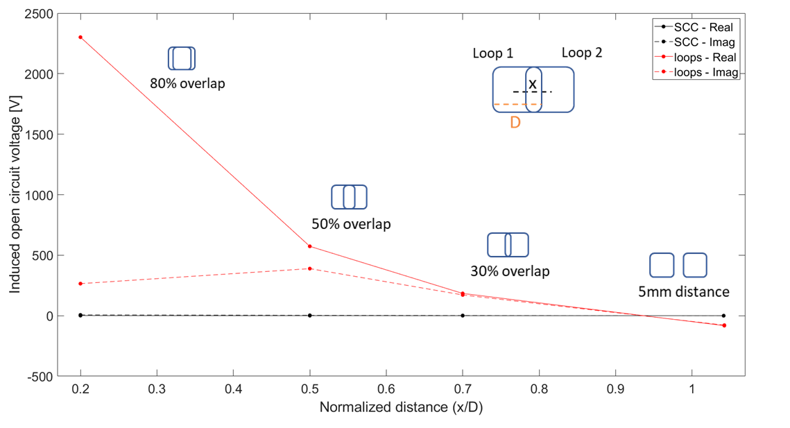
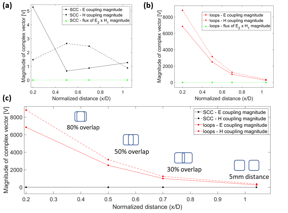
Figure 2 shows that in each configuration the induced voltage was negligible for the SCCs as compared to the loops. The average relative difference between expression (1) and $$$V_{21}$$$ by CST was -1.8% for the real part and 2.7% for the imaginary part.Figure 3 shows that the value of the term $$$\oint_S ( \textbf{E}_{2}\times \textbf{H}_{1} ) \cdot d\textbf{S}$$$ was negligible as compared to the electric and magnetic coupling terms. The SCCs showed much less electric and magnetic coupling contributions compared to the loops.
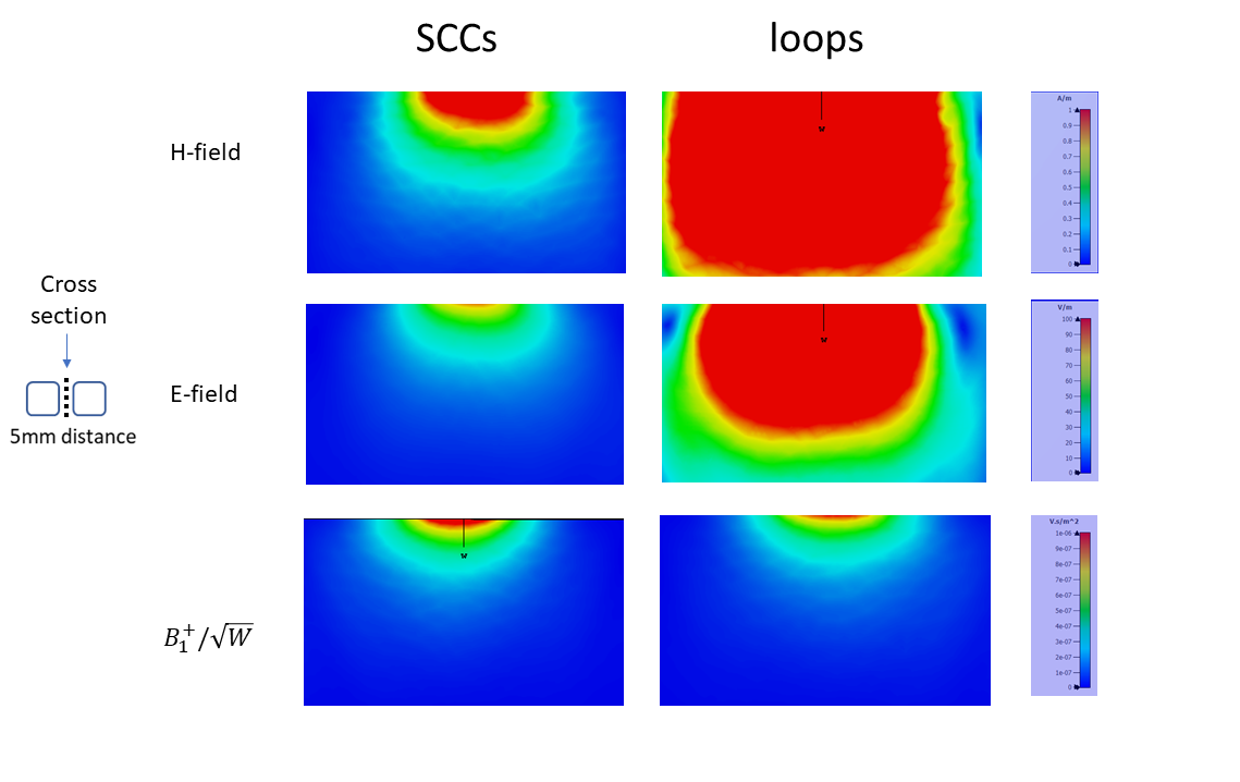
Figure 4 shows that the magnitude of the E and H fields were significantly lower in the SCC case, with comparable value of the magnitude of B1+/√W
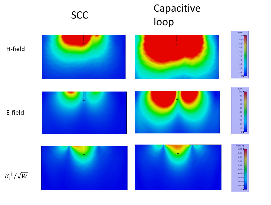
Figure 5 shows the magnitude of the E, H, B1+/√W field in a central cross section, in the case of a single capacitive-segmented loop, and in the SCC case. Plots were generated using 1A of current at the ports. The magnitude of the E and H fields was still lower in the SCC case, with comparable magnitude of B1+/√W.
Discussion
Both electric and magnetic coupling were lower in SCCs. From expression (1) we deduce that lower electric (magnetic) coupling can be either related to orthogonality between two radiation profiles, or lower average amplitude of the fields E1(H1) and/or E2(H2).To discriminate between these two effects, we examined the plot of the E and H fields in a central cross-section of the phantom. We note that in every configuration the E and H fields -which determine SAR in the tissue- were lower in the SCC case, with comparable magnitude of the B1+/√W field -which determine SNR in the image.
It is well known that capacitors block the radiation of the E field. Therefore, we compared the E, H and B1+/√W fields of a SCC with the E, H and B1+/√W field of a capacitive-segmented loop. To make the two plots comparable, we considered the fields radiated for 1A of current at the ports. We note that the E and H field were lower in the SCC case.
Conclusions
In this work, we discuss coupling in SCCs and further implications in the design of MRI coils. We demonstrate that lower coupling in SCCs derives from lower magnitude of the E and H fields in the calculation volume, with comparable magnitude of the B1+/√W field. Further, we show that a shield is more effective than using capacitors to block the propagation of the E and H fields.Acknowledgements
No acknowledgement found.References
1. T. Ruytenberg, A. Webb, and I. Zivkovic, “A flexible five-channel shielded-coaxial-cable (SCC) transceive neck coil for high-resolution carotid imaging at 7T”, Magn Reson Med. 2020; 84:1672–1677
2. T. Ruytenberg, A. Webb, and I. Zivkovic, “Shielded-coaxial-cable Coils as Receive and Transceive Array Elements for 7T Human MRI.” Magn Reson Med (2019) 83(3):1135–46.
3. R. F. Harrington, “Time-Harmonic Electromagnetic Fields.” Piscataway, NJ, USA: IEEE Press, 2001
4. V. H. Rumsey, “The Reaction Concept in Electromagnetic Theory”, Phys. Reo., sere 2, vol. 94, no. 6, pp. 1483-1491, 1954
5. P.B. Roemer et al. , “The NMR phased array”, in Magnetic Resonance in Medicine, vol. 16, pp.192-225, 1990
6. Constantinides, C D et al. “A phased array coil for human cardiac imaging.”, in Magnetic resonance in medicine vol. 34, n. 1, pp. 92-98, 1995
7. J.-S.Hong , “Couplings of asynchronously tuned coupled microwave resonators”, IEE Proc. Microw, Antenna and Propag., Vol. 147. No. 5, Ucloher 2000
8. J.-S. Hong, M. J. Lancaster, “Microstrip Filters for RF/Microwave Applications”, John Wiley & Sons, Inc. , 2001
9. I. Awai and Y. Zhang, “Maxwell equations coupled mode theory and coupling coefficient” , Proc. of Asia Pacific Microwave conference 2014, 1223-1225
10. I. Awai and Y. Zhang, “Separation of Coupling Coefficient Between Resonators into Magnetic and Electric Components Toward Its Application to BPF Development” , 2008 China-Japan Joint Microwave Conference, 61-65
11. I. Awai and Y. Zhang, “Coupling Coefficient of Resonators—An Intuitive Way of Its Understanding”, Electronics and Communications in Japan, Part 2, Vol. 90, No. 9, 2007
12. Xinqiang Yan, John C. Gore, William A. Grissom, “Self-decoupled radiofrequency coils for magnetic resonance imaging”, Nature Communications, 9:3481, pp. 1-12, 2018
13. G. Costa, , S. Güler , P. Baltus, M. Paulides, I. Zivkovic, “Investigation of correlation between surface current and coupling using conventional coils and shielded coaxial cable coils operating at 7T”, Proc. Int. Soc. For Mag. Reason. Med., 2022
Figures