4245
Inductive and capacitive coupling modes of an RF coil to an ultra-High Dielectric Constant (uHDC) disk resonator1Center for NMR Research, Departments of Neurosurgery and Radiology, College of Medicine, Pennsylvania State University, Hershey, PA, United States, 2Center for Magnetic Resonance Research, University of Minnesota, Minneapolis, MN, United States, 3Department of Engineering Science and Mechanics, Pennsylvania State University, State College, PA, United States
Synopsis
Keywords: Non-Array RF Coils, Antennas & Waveguides, High-Field MRI, Coil, Dielectric, coupling, SNR
We investigated capacitive and inductive couplings of an RF coil to an ultra-High Dielectric Constant (uHDC) disk resonator with a given resonance mode of similar frequency using simulation and experiments. Coupling of the RF coil and uHDC resonator can result in splitting the resonance into two modes: a parallel mode via inductive coupling and an anti-parallel mode via capacitive coupling. With the two resonators, the stronger and deeper penetration of the resultant B1 field is observed with parallel mode (in-phase) than anti-parallel mode (out-of-phase), which supports that the parallel mode is preferable for coupling uHDC resonators for MRI applications.Introduction:
Dielectric resonators with a high dielectric constant possess intrinsic resonance modes that have been investigated for enhancing RF coil’s transmit efficiency and receive sensitivity. For low field MRI or low-g X-nuclei MRS at high field applications, the permittivity of the material must be increased up to 2000 to 6000, herewith termed ultra-High Dielectric Constant (uHDC)1. In this case, the RF coil near the uHDC resonator with a similar resonance frequency is complicated by a strong capacitive coupling between the two resonators, generating two split resonance modes: a parallel and antiparallel mode. As such, tuning and matching to the two modes to a desirable frequency becomes difficult. Further, it is important to understand the characteristics of the resultant B1 field of corresponding to the two modes produced by the two strongly coupled resonators when an RF coil operates closely with the uHDC resonator.Method:
The simulation setup (Figure 1) compromised of uHDC disk (diameter = 8.3cm, height = 1.4cm) with the first intrinsic resonance mode at 62MHz coupled with a double-loop spiral surface coil (diameter = 9 cm) tuned and matched to the same frequency, preloaded 2. Then it is loaded with “Duke” human head voxel model (Figure 1(b)). When both resonators were close to each other, we observed two resonance modes as illustrated in Figure 1(c). The resonance modes and conditions of the uHDC disk and coil were studied through both computer simulations and benchtop measurements. The computer simulations were performed using the electromagnetic solver CST Microwave Studio (CST MWS). We compared the H-field and the receive (Rx) sensitivity of both split resonant modes with a conventional 9 cm diameter surface coil as the baseline.The experimental setup is illustrated in Figure 2(a), for both unloaded and loaded condition. Transmission coefficient (S12) from resonators to the sniffer coil and the magnetic field for both unloaded and loaded conditions were measured and compared with varied distance (Figure 2(b)).Results:
The fundamental mode of the uHDC disk resonator is first transverse electric mode, TE01δ, at 62MHz which produces a strong H-field in the phantom shown in Figure 3(a) and 3(b) for both simulation and measurement. By loading a phantom to the coil placed near the uHDC resonator, which are resonating at 62 MHz, the split resonances were observed at 52.5MHz and 78.5MHz. (Figure 1(c)). In Figure 4(a) and (b), the simulated H-field distribution is shown for both split modes, a parallel mode via inductive coupling and an anti-parallel mode via capacitive coupling. As seen in the vector plot, the H-fields by the RF coil and uHDC disk are in-phase for parallel mode at 52.5MHz, producing a stronger Rx-sensitivity along the central axis of the coil as well as in most part of brain, while those of anti-parallel mode at 78.5 MHz are out-of-phase, resulting in a weaker H-field strength in the phantom as shown in Figure 4(c) and 4(d). The H-field of parallel mode has deeper penetration compared to the anti-parallel mode which has inhomogeneous H-field distribution and leads to decreased overall Rx sensitivity. The Rx sensitivity at two different modes, in which the coil tuned at 62MHz and loaded with the uHDC resonator, is shown in Figure 5. The Rx sensitivity is significantly increased at the presence of the uHDC disk versus baseline at first parallel mode. This enhancement region reaches 7cm deep into the phantom. In Figure 5(b) and 5(c), the measured results of S12 are shown at different matching conditions (1st and 2nd mode, respectively) and different distance between a sniffer coil and two combined resonators of the RF coil with the uHDC disk. Based on Table I, it is shown that the 1st mode has higher penetration depth for two different modes.Discussions and Conclusion:
When the RF coil is loaded with and coupled to the uHDC disk with a similar resonance frequency, two split modes below and higher than the fundamental mode frequency of the uHDC disk were induced. These two modes were produced via two different coupling mechanisms. The parallel mode is produced by sharing the H-field flux between the two resonators. In this mode, the H-fields produced by the RF coil and the uHDC disk are in-phase via induced displacement current in the dielectrics, different from those with a coil via induced conductive current in the wire. The anti-parallel mode is produced by capacitive coupling between two resonators, in which the H-field is produced by time-varying electric charges induced on the surface of the dielectric. In this case, the H-fields by the coil and the uHDC disk are out-of-phase and distractive superimposed and result in reduced B1 penetration depth. We have calculated the Rx sensitivity for two resonant modes for different positions inside the phantom. Numerically and experimentally, we observed that the parallel mode has significantly higher Rx sensitivity. Therefore, to achieve the best focusing effect into phantom, the RF coil design with uHDC material should operate around the first mode with the frequency lower than the second mode TE01δ).Acknowledgements
Acknowledgment: This work was supported in part by NIH grants of U01 EB026978, R01 CA240953 and P41 EB027061.References
1. Chen, W., et al., Tunable Ultrahigh Dielectric Constant (tuHDC) Ceramic Technique to Largely Improve RF Coil Efficiency and MR Imaging Performance. IEEE Trans Med Imaging, 2020. 39(10): p. 3187-3197.
2. Roemer, P B et al. “The NMR phased array.” Magnetic resonance in medicine vol. 16,2 (1990): 192-225. doi:10.1002/mrm.1910160203
Figures
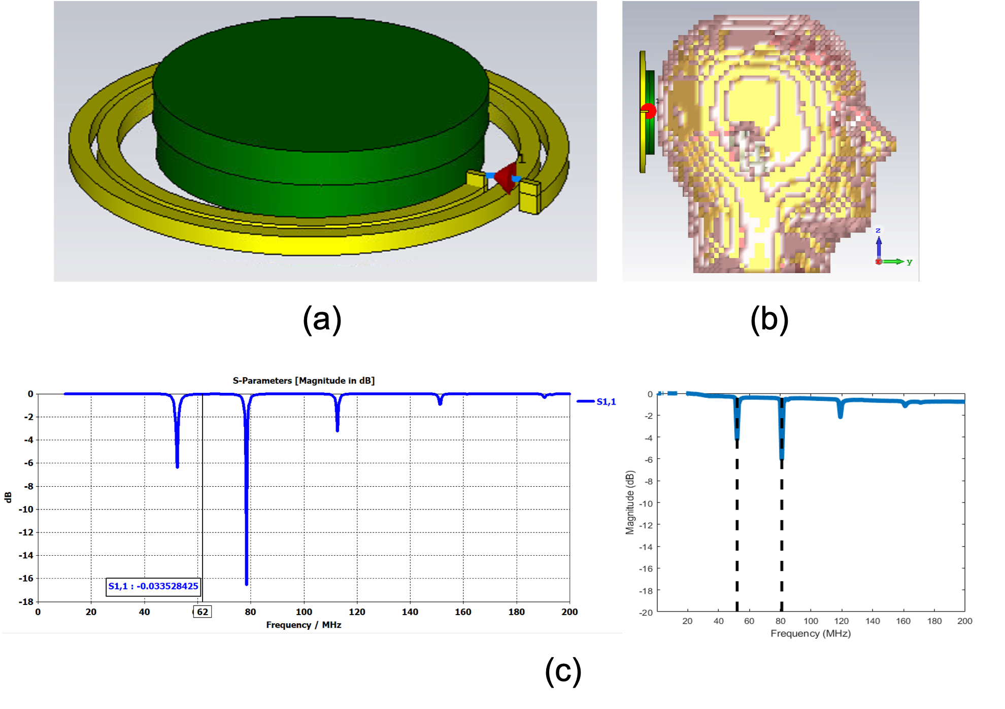
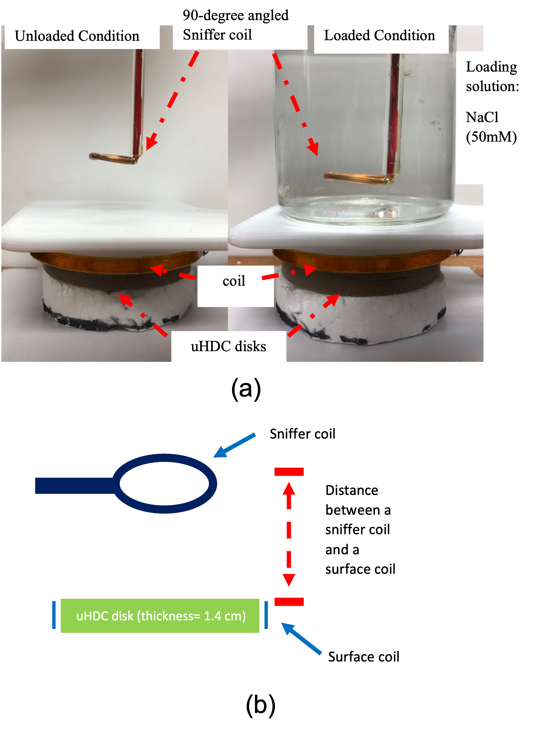
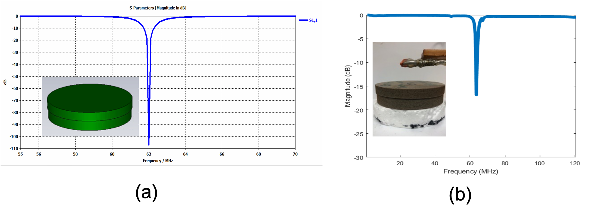
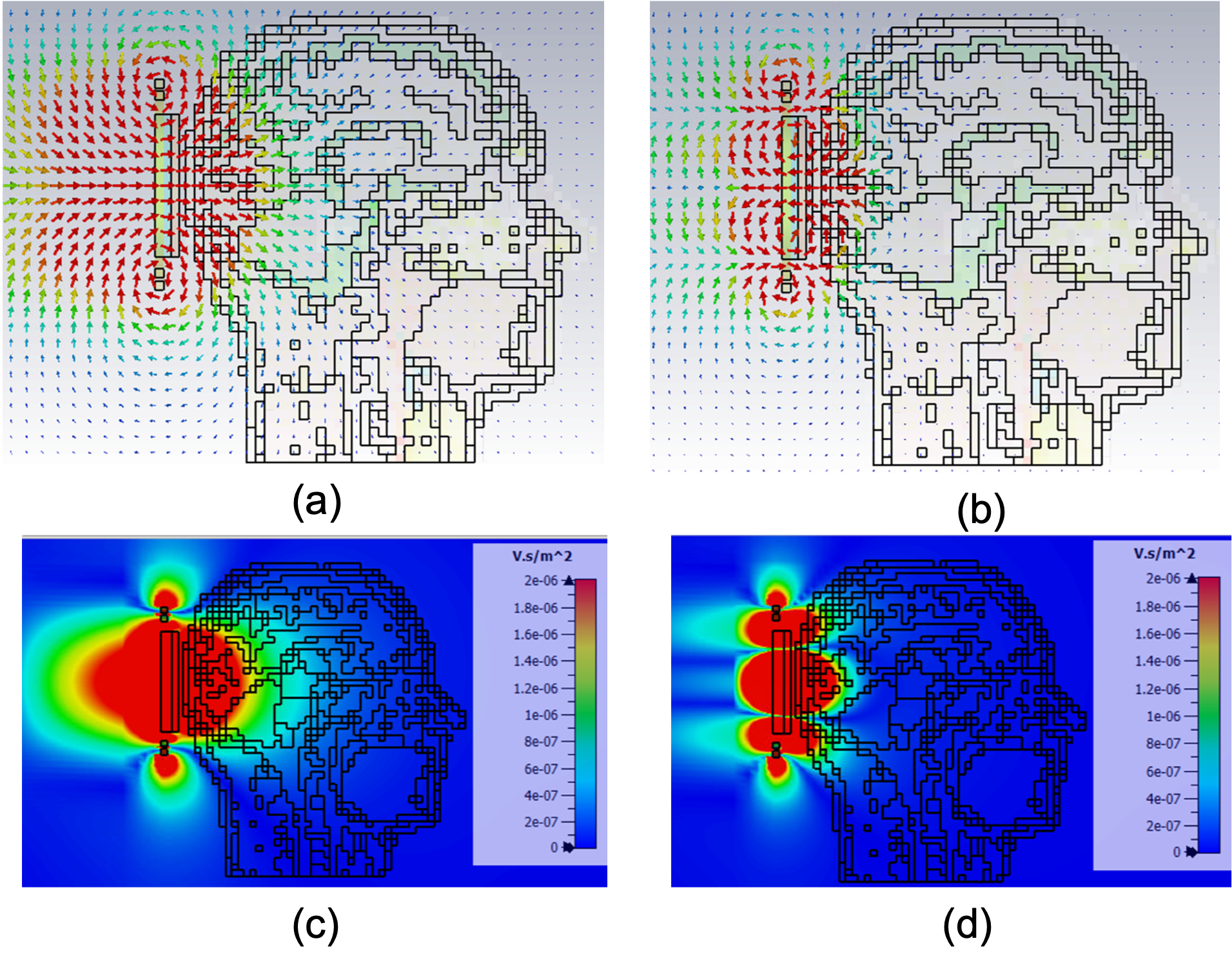
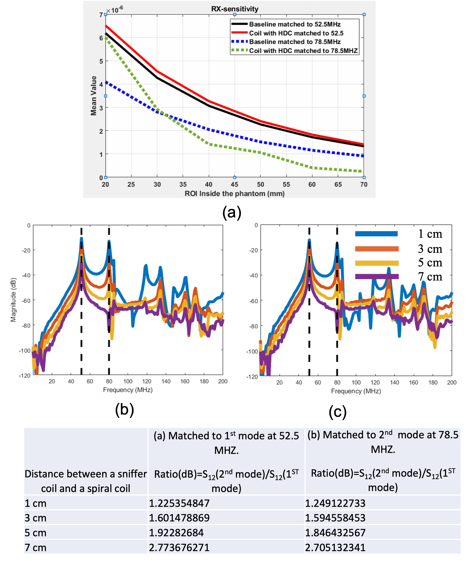
Table I: The ratio of S12 between two resonance modes, (a) The design was matched to 52.5MHz, (b) the design was matched to 75.5MHz.Figure 5: (a) The simulated Rx sensitivity of baseline (excited with 9cm conventional loop) and with the uHDC disk for two different split modes at 52.5MHz and 78.5MHz, (b) Measurement results of S12 at different distance between a sniffer coil and surface coil which was matched to 52.5MHz, (c) S12 at different distance between a sniffer coil and surface coil which was matched to 78.5MHz.