4244
Characterization of the RF field for metamaterial-based structures constructed of conducting strips and a dielectric at 7T MRI1Brain Sciences, Weizmann Institute of Science, Rehovot, Israel, 2Department of Brain Sciences, Weizmann Institute of Science, Rehovot, Israel
Synopsis
Keywords: New Devices, High-Field MRI
Metamaterial-based structures constructed of conducting strips and a dielectric have already been used to locally increase the RF transmit field. In this study we characterize the RF field of such structures at 7T MRI. Configurations included either long strips (representing electric dipoles), or a matrix of short strips (representing magnetic dipoles). The RF field dependence on strip density and distribution was analyzed, providing insights useful for efficiency and coverage optimization. The configuration based on a matrix of short strips provides higher RF transmit efficiency, while the use of a non-uniform concave distribution of strips is useful to lower SAR.Introduction
Ultra-high field MRI provides an increased SNR but also new opportunities to explore novel schemes to increase both RF transmit efficiency and signal reception. Recent works have demonstrated new metamaterials approaches viable in MRI1-3. One such approach, that was already demonstrated at 1.5 T and 7T MRI, combines a dielectric substrate with conducting strips4-6. This design provides a more compact setup than using only a dielectric. A resonant transverse electric mode, which is useful in MRI, can be implemented with this approach using two configurations – one based on an array of long strips4,5, representing an electric dipole system, and another based on a matrix of short strips6,7, similar to a set of split-rings, which represents a magnetic dipoles system. In this study, these configurations are compared. Furthermore, characterization of the sub-units properties – including the effect of the number of conducting strips and their in-plane distribution (uniformly and non-uniformly spaced strips) - is examined to realize an optimal design.Methods
Examined setups: Four configurations of metamaterial-based structures, consisting of a dielectric layer and copper strips, were compared. The total dimensions for all setups were kept the same - 16x11x0.7 cm3 (length, width and thickness, respectively).The details of the four setups are:
i) An array of long strips, representing Electric Dipoles, with Uniformly spaced copper lines (‘ED-UL’). Used a dielectric with relative permittivity (εr)=72 and six copper strips equidistantly spaced, 20 mm apart. ii) An array of long strips, representing Electric Dipoles, with Non-Uniformly spaced copper lines (‘ED-NUL’). Used a dielectric with εr=76 with six copper strips spaced 10, 20, 40, 20 and 10 mm apart.
iii) A matrix of short strips, representing Magnetic Dipoles, with Uniformly spaced copper lines (‘MD-UL’). Used a dielectric with εr=164 and strips spaced as in i).
iv) A matrix of short strips, representing Magnetic Dipoles, with Non-Uniformly spaced copper lines (‘MD-NUL’). Used a dielectric with εr=160 and strips spaced as in ii).
EM simulations: The characterization of the resonant modes was performed using an eigen-mode solver with the frequency of the deepest transverse electric mode adjusted to 298 MHz. The H- and E-fields were then compared and the average |H|/|E| ratio (over a 160x110 mm2 square) was calculated for different setups. 3D EM simulations of the B1+ field were performed using the FIT (finite integration technique) software (CST Microwave Studio, Darmstadt, Germany). All B1+ maps were normalized to an accepted power of 1 Watt. The simulation setup included a 16-rung high-pass quadrature birdcage coil (inner diameter 30 cm; rung length 18 cm). The simulations were performed using the same phantom as in the real setup as well as with a human model. The phantom electrical properties were εr=53 and conductivity (σ)=0.3 S/m. The human model was “Duke” from the Virtual family using a mesh resolution of 1.0 x 1.0 x 1.0 mm3. In these human model simulations the metamaterial-based structure was curved to best fit the shape of the head.
Phantom scanning: The metamaterial-based designs were placed on top of the phantom and scanned in a 7T MRI (MAGNETOM Terra, Siemens Healthcare, Erlangen) with the 1Tx/32Rx Nova coil. Scans using the vendor’s B1 map sequence were collected using a 20x20 cm2 FOV and spatial resolution 2.5 x 2.5 x 3.5 mm3.
Results
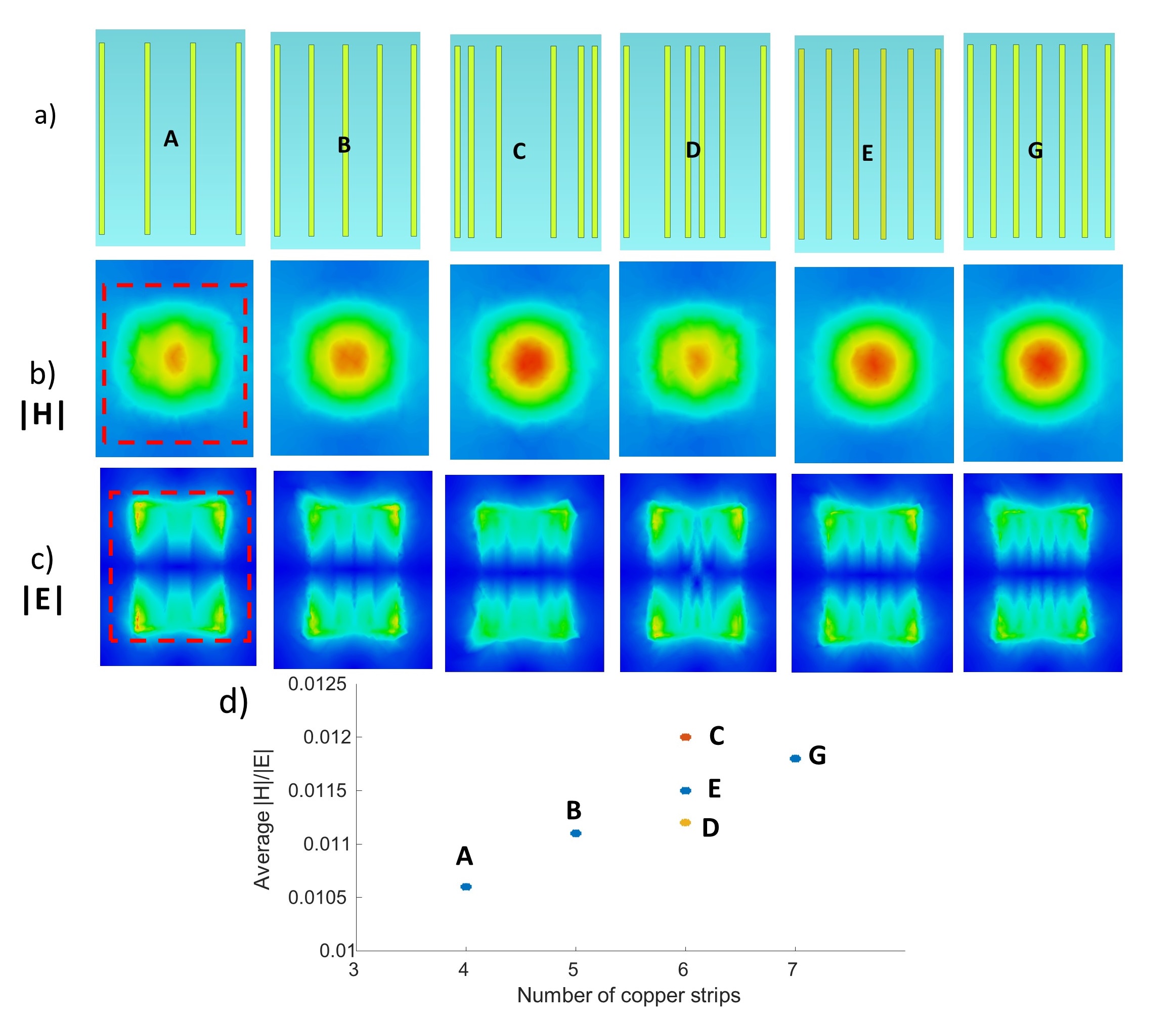
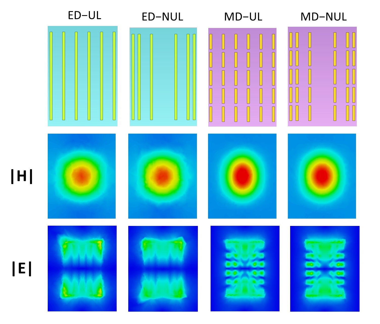
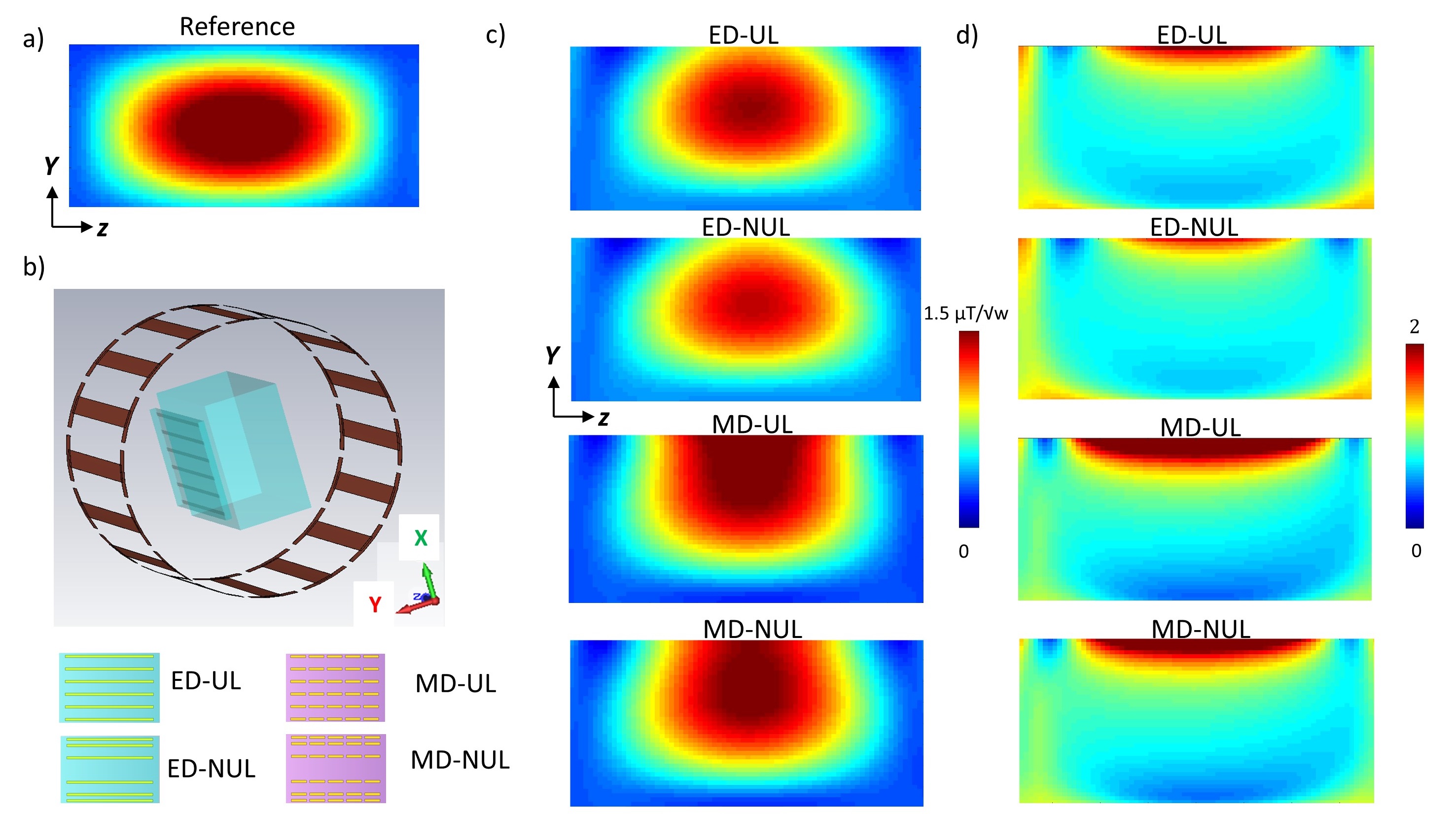
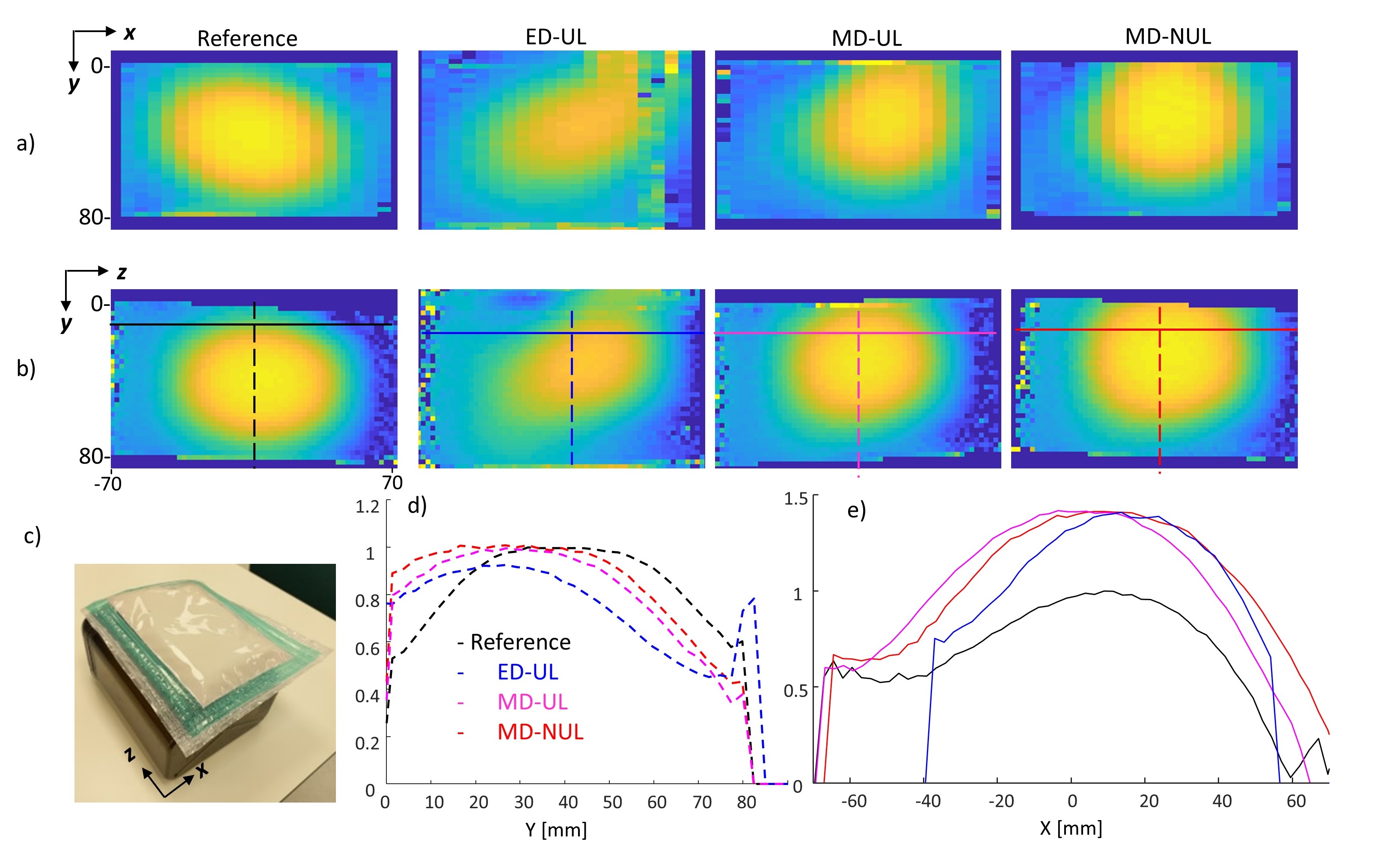
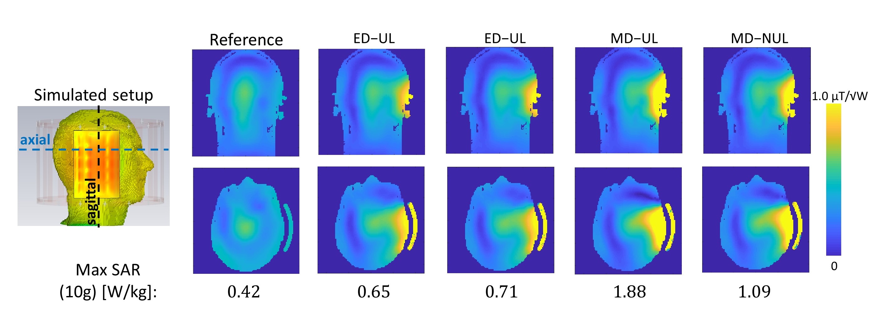
Figure 1 shows the |H| and |E| maps at 20 mm and 5 mm from the structure, respectively, and the average |H|/|E| ratio as function of the strips density and distribution. Increasing the number of strips increased the |H|/|E| ratio, which offers increased efficiency. A convex distribution (denser in the center, Fig. 1D) resulted in a lower |H|/|E| ratio, while a concave distribution (denser at the edges, Fig. 1C) increased the ratio. Figure 2 shows the |H| and |E| fields for the long and short strip configurations. Figure 3 shows the EM simulations of the phantom and the four configurations, demonstrating a higher B1 and deeper coverage using the short strips design. Figure 4 shows the measured B1 maps in phantom, demonstrating a larger coverage in Z and Y directions (in parallel to the structure and deeper into the phantom) using the ‘MD-NUL’ structure (and also more symmetric compared to ‘MD-UL’). Figure 5 shows the simulations of a full setup, including human brain, with the metamaterial-based structures. The B1 maps show that ‘MD-NUL’ provides increased B1 field coverage. The maximal SAR value for the short strips design is higher compared to the uniform one, but the ‘MD-NUL’ configuration helps to reduce the SAR. The ‘MD-NUL’ structure provides a local maximal B1 enhancement of x2.95 and a x1.57 transmit efficiency (Max B1/√Max SAR).Conclusions
In this study, a characterization of the RF field distribution as function of the strip density and distribution was performed, providing insights useful for efficiency and coverage optimization. The configurations based on long strips (‘ED-UL’ and ‘ED-NUL’) offer lower SAR, while the configurations based on short strips (‘MD-UL’ and ‘MD-NUL’) offer greater enhancement and coverage. The ‘MD-NUL’ configuration provides higher B1, but also reduces the SAR compared to the ‘MD-UL’ configuration.Acknowledgements
No acknowledgement found.References
1. Algarín, J. M., Freire, M. J., Breuer, F., & Behr, V. C. (2014). Metamaterial magnetoinductive lens performance as a function of field strength. Journal of Magnetic Resonance, 247, 9-14.
2. Gomez, T. S. V., Dubois, M., Rustomji, K., Georget, E., Antonakakis, T., Vignaud, A., ... & Abdeddaim, R. (2022). Hilbert fractal inspired dipoles for passive RF shimming in ultra-high field MRI. Photonics and Nanostructures-Fundamentals and Applications, 48, 100988.
3. Lippke, M., Stoja, E., Philipp, D., Konstandin, S., Jenne, J., Bertuch, T., & Günther, M. (2022, September). Investigation of a Digitally-Reconfigurable Metasurface for Magnetic Resonance Imaging. In 2022 52nd European Microwave Conference (EuMC) (pp. 668-671). IEEE.
4. Slobozhanyuk, A. P., Poddubny, A. N., Raaijmakers, A. J., van den Berg, C. A., Kozachenko, A. V., Dubrovina, I. A., ... & Belov, P. A. (2016). Metasurfaces: Enhancement of Magnetic Resonance Imaging with Metasurfaces (Adv. Mater. 9/2016). Advanced Materials, 28(9), 1831-1831.
5. Schmidt, R., Slobozhanyuk, A., Belov, P., & Webb, A. (2017). Flexible and compact hybrid metasurfaces for enhanced ultra high field in vivo magnetic resonance imaging. Scientific reports, 7(1), 1-7.
6. Schmidt, R., & Webb, A. (2017). Metamaterial combining electric-and magnetic-dipole-based configurations for unique dual-band signal enhancement in ultrahigh-field magnetic resonance imaging. ACS applied materials & interfaces, 9(40), 34618-34624.
7. Dolling, G.; Enkrich, C.; Wegener, M.; Zhou, J. F.; Soukoulis, C. M.; & Linden, S. Cut-wire Pairs and Plate Pairs as Magnetic Atoms for Optical Metamaterials. Opt. lett.., 2005, 30(23), 3198-3200.
Figures