4243
End-Grounded Dipole RF Element with Extended Coverage and Minimized SAR at 7T MRI1the University of Queensland, Brisbane, Australia, 2School of Electronic Engineering (National Key Laboratory of Antennas and Microwave Technology) and Hangzhou Institute of Technology, Xidian University, Hangzhou, China, 3Zhejiang University, Hangzhou, China
Synopsis
Keywords: RF Arrays & Systems, RF Arrays & Systems
Dipole RF coil suffers from high peak local SAR and limited imaging coverage. In this work, a novel dipole structure is proposed. Compared with the fractionated dipole, the proposed design achieves a substantially enlarged B1 field coverage and more than 25% SAR reduction by generating a uniform surface current on the coil. Experimental validations were conducted and agreed well with the simulation results.
Introduction
The dipole RF coil has been intensively developed in ultra-high field MRI owing to the better transmit penetration depth and higher efficiency1. However, a conventional dipole coil suffers from the current concentration at its centre (where the feeding port locates), which leads to a nonuniform B1 field distribution and high peak specific absorption rate (pSAR). Specifically, the concentrated surface currents on a conventional dipole coil not only reduce the transmit field fast towards two ends but also exhibit a relatively high heating effect near the feeding port. This work proposes a new structure that can enhance the uniformity of current distribution along the coil. The image coverage along the longitudinal direction was substantially extended, and the SAR was largely reduced.Methods
The proposed end-grounded dipole (EGD) coil is shown in Fig.1. The coil has two identical layers with a length of 300mm, separated by an acrylic board for the supporting purpose. Each layer is equally separated by three gaps to mount lumped elements. The two layers are connected by microstrip lines at each end with a separation distance of 10mm. The feeding port is placed at the centre of the far side layer from the loading. Two capacitors with a capacitance of 1 pF and three inductors with an inductance of 1 nH are mounted on the far side and loaded side of the coil. The loaded side is defined as the layer of the coil that faces the loaded subject and produces a primary of the B1 field. Consequently, the impedance at the ends of the dipole is reduced; thus, the weakened currents caused by the open circuit at the ends of the conventional dipole coil are augmented, and as a result, more uniform and stronger current distributions can be achieved at the loaded side of the coil. Meanwhile, the coil is tuned at 297.2MHz (the working frequency of 7T MRI system) and matched with a reflection coefficient better than -20 dB. Full-wave simulations were performed using Sim4life (Zürich, Switzerland). The proposed design is assessed using a body-shaped phantom with tissue-like properties ($$$\epsilon_{r}=74.1,\sigma=0.66 s/m$$$) (Fig. 1D). The distance between the coil and phantom is 20mm (Fig. 1B). The 10g-average peak local SAR and $$$B_1^+$$$ field are used to calculate the SAR efficiency as $$$B_1^{SAR}=B_1^+/\surd{MAX(SAR_{10g})}$$$. To verify the design concept, a fractionated coil3 with the same length is used to compare with the proposed structure. The two coils were fabricated and tested on a 7T MRI scanner for experimental validations.Results and Discussion
Simulated surface current distributions on the EGD coil and fractionated coil are shown in Fig.2A-B. Compared with the fractionated dipole, the EGD coil generates a more uniform and stronger current distribution, particularly at the ends of the coil, which verifies the design concept. Simulated SAR efficiency and SAR10g distribution in axial and sagittal planes are shown in Fig. 3A-B. All results were normalized to 1 W accepted power. It can be seen that the transmitted field area is extended because of the enhanced uniformity of current distribution. Meanwhile, SAR10g is significantly reduced because of the reduced concentration of current near the feeding port. Fig. 4 shows the line plots extracted from the dashed lines in Fig. 3. Compared with the fractionated dipole, improved SAR efficiency can be achieved not only near the surface but also in the deeper region of the phantom. The SAR10g is reduced in the shallow region (i.e., the region where maximum SAR10g is typically present) of the phantom where the maximum local SAR10g is reduced from 1.65 W/kg to 1.21 W/kg, which corresponds to a 27% reduction. Fig.5 B-C show the flip angle maps using the AFI method4 on a 7T MRI scanner (Fig.5 A). The measured results agree well with the simulation results, stating that the proposed coil largely improves the longitudinal coverage with comparable penetration depth.Conclusion
The proposed EGD coil is proven feasible for applications requiring a large field of view, especially in longitudinal direction. Peak local SAR is reduced because of the uniform surface current on the coil. Future studies will focus on demonstrating the improvement by a multi-channel array and its application in pTX for torso imaging.Acknowledgements
No acknowledgement found.References
[1] A. J. E. Raaijmakers, P. R. Luijten, and C. A. T. van den Berg, “Dipole antennas for ultrahigh-field body imaging: a comparison with loop coils,” NMR Biomed., vol. 29, no. 9, pp. 1122–1130, 2016, doi: 10.1002/nbm.3356.
[2] C. C. van Leeuwen, B. R. Steensma, D. W. J. Klomp, C. A. T. van den Berg, and A. J. E. Raaijmakers, “The Coax Dipole: A fully flexible coaxial cable dipole antenna with flattened current distribution for body imaging at 7 Tesla,” Magn. Reson. Med., vol. 87, no. 1, pp. 528–540, 2022, doi: 10.1002/mrm.28983.
[3] A. J. E. E. Raaijmakers et al., “The fractionated dipole antenna: A new antenna for body imaging at 7 Tesla,” Magn. Reson. Med., vol. 75, no. 3, pp. 1366–1374, 2016, doi: 10.1002/mrm.25596.
[4] V. L. Yarnykh, “Actual flip-angle imaging in the pulsed steady state: A method for rapid three-dimensional mapping of the transmitted radiofrequency field,” Magn. Reson. Med., vol. 57, no. 1, pp. 192–200, Jan. 2007, doi: 10.1002/MRM.21120.
Figures
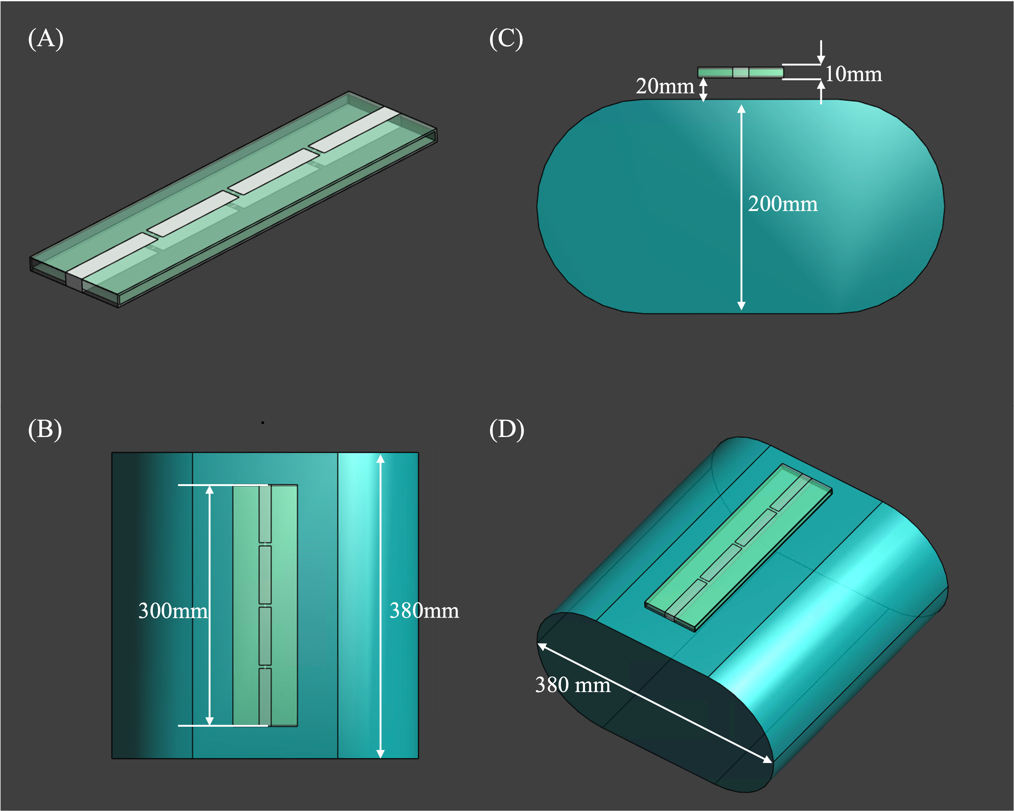
Fig. 1 A: The proposed coil and fractionated dipole. B: The top view and dimensions of simulation configuration using a body-shaped phantom. C: The side view of modelling configuration. D: Three-dimensional view and dimensions of the body-shaped phantom.
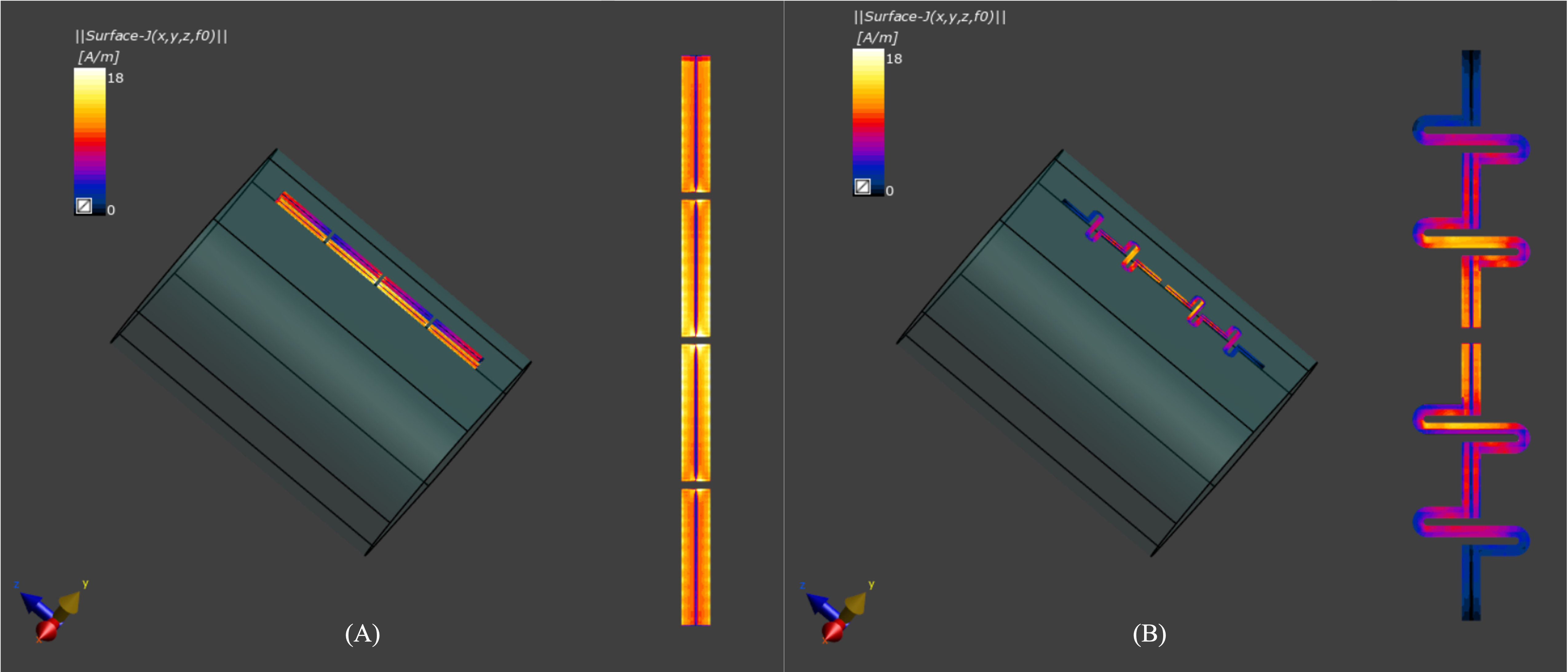
Fig. 2 A: The current distribution on the proposed coil. B: The current distribution on the fractionated coil.
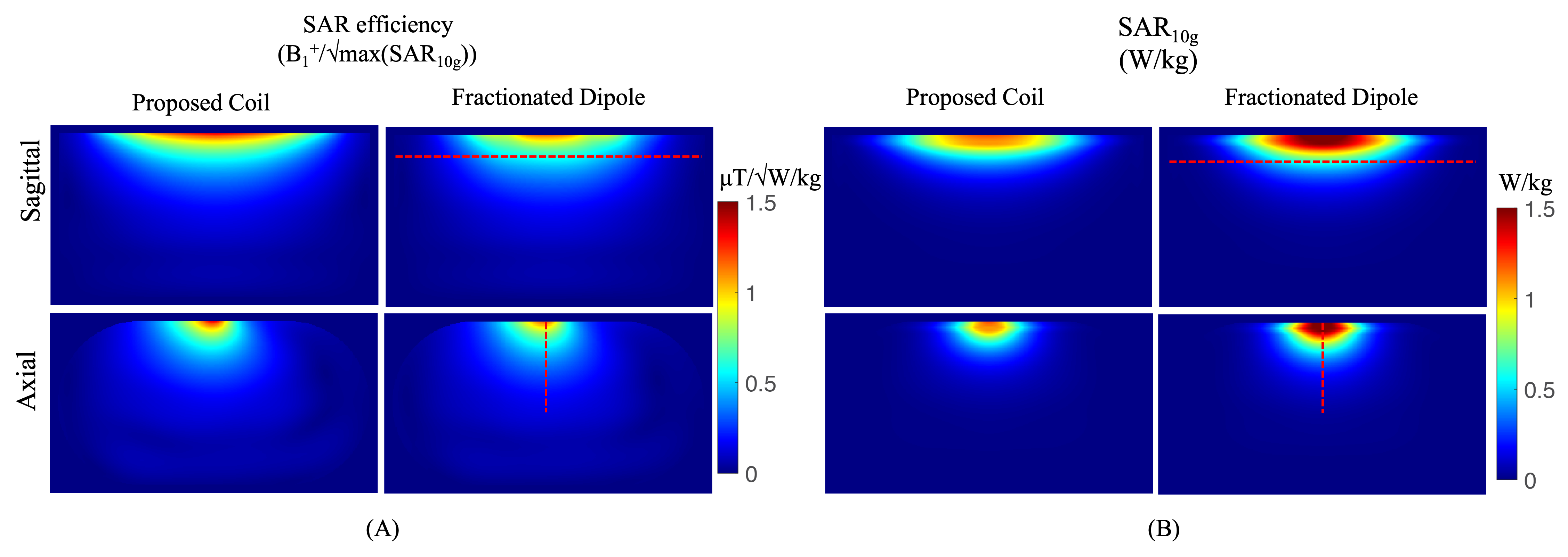
Fig. 3 A: Simulated SAR efficiency distributions inside the phantom in axial and coronal planes. B: Simulated SAR10g distribution inside the phantom in axial and coronal planes. The left column of A and B shows the results from using the proposed coil, and the right column of A and B shows the results from using a single HPP.
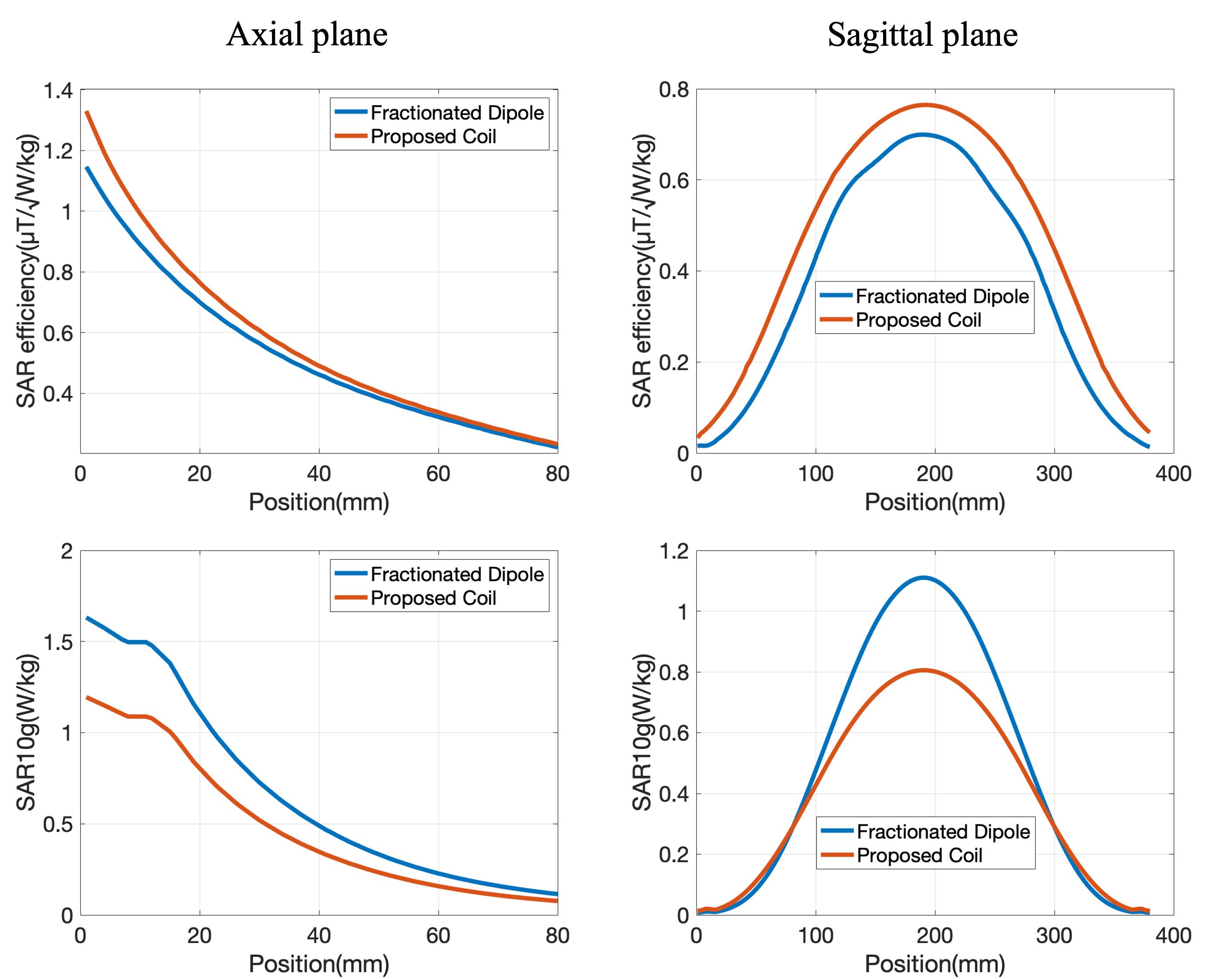
Fig. 4 Line plots of SAR efficiency and SAR10g along the dashed lines shown in Figure 3. The selected lines at the axial plane cross the centre of the planes, and the selected line at the sagittal plane is 30 mm away from the top of the phantom.
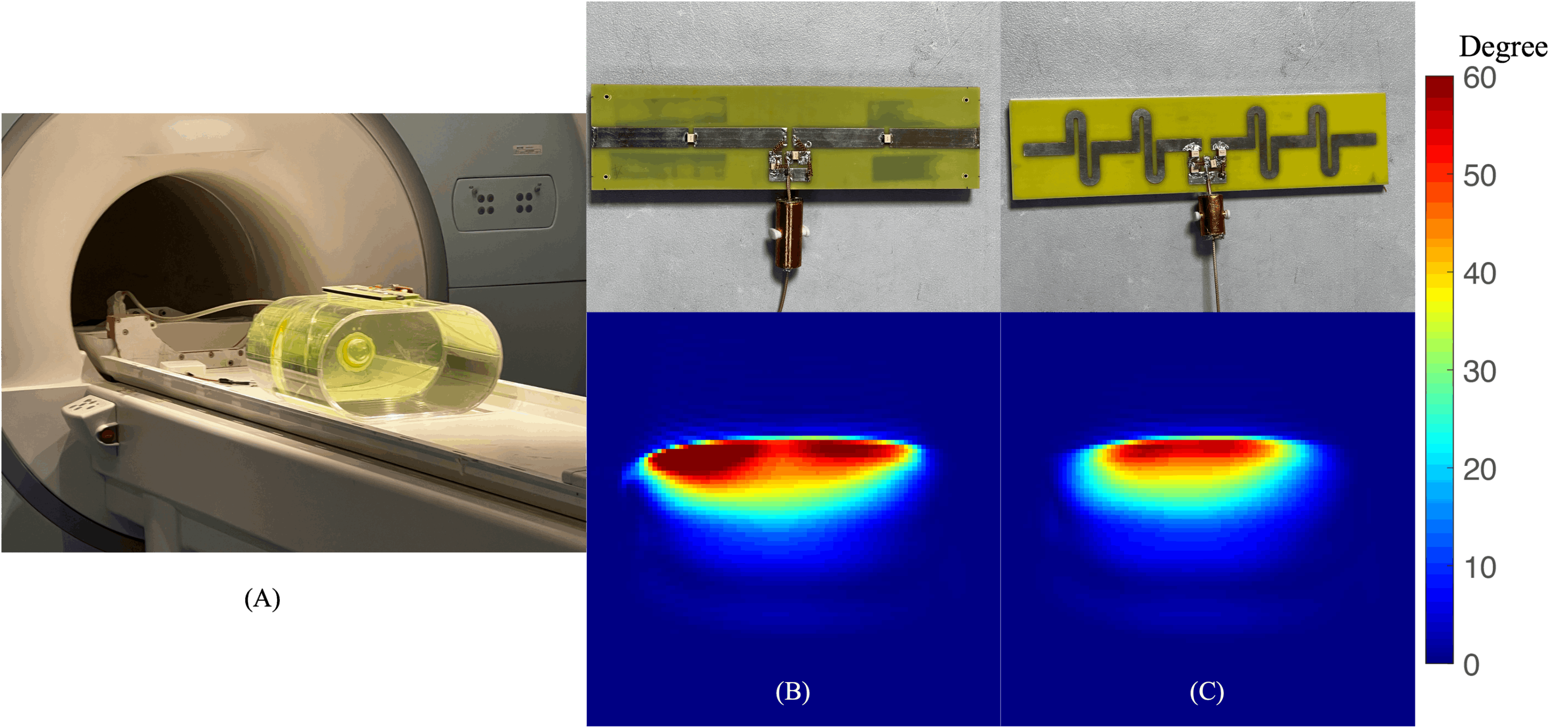
Fig. 5. A: The experimental setup for the B1 mapping using the AFI method. B: The manufactured proposed coil and its flip angle map. C: Manufactured fractionated dipole and its flip angle map.