4242
FAIR Benchmarking of 7T MRI Antennas – Case for a Standardized Protocol for RF Transmit Element Performance Assessment1Siemens Healthineers GmbH, Magdeburg, Germany, 2Otto-von-Guericke University, Magdeburg, Germany, 3Berlin Ultra-High Field Facility, Max-Delbrück Center for Molecular Medicine in the Helmholtz Association, Berlin, Germany, 4Research Campus STIMULATE, Magdeburg, Germany
Synopsis
Keywords: Non-Array RF Coils, Antennas & Waveguides, Non-Array RF Coils, Antennas & Waveguides
This abstract proposes a standardized setup and four standardized metrics to increase 7T Tx RF antenna concept comparability and reproducibility, with the goal of a better technology transfer of antenna concepts across the MR community. Eight antenna concepts are evaluated based on power and SAR efficiency as well as mutual coupling and reliance on load changes using a rectangular phantom mimicking the average electromagnetic body properties. Based on the presented results, much information can be collected and deductions about each antenna's preferable ambits drawn. In conclusion, this work initiates a first standardized protocol for analyzing Tx RF antenna concepts.Introduction
The benefits of UHF are hampered by $$$ \text B _1^+$$$ heterogeneity and SAR constraints1,2. Directions that address these challenges involve the development of new RF antenna concepts3-9, where each concept is designed and optimized for a specific application and setup. Additionally, the evaluated performance benchmarks can vary1-9. To date, no common standard on performance benchmarks nor on evaluation setups of Tx arrays exist. This abstract initiates and promotes discussion and development of a standardized method for RF antenna evaluation to enhance comparability, and reproducibility, to achieve broad applicability and technology transfer of RF antenna concepts across the MR community.Material and Methods
For benchmarking, eight antenna concepts were evaluated within this work depicted with dimensions in figure 13-9. As standardized setup, a homogeneous phantom mimicking the average electromagnetic human body properties (dimensions and parameters are provided in figure 2a) was placed 2cm underneath each antenna, which is a common distance between transmit elements and the load4,6,8-10. The phantom was chosen to minimize effects of curvature or heterogeneity and to make the construction of the phantom as simple as possible. These simulations are performed in CST Microwave Studio 2022’s time domain solver at a resonance frequency of 297.2MHz, but any other simulation software could have been used. The antennas are taken from and simulated as described in the corresponding literature.As benchmark parameters the power efficiency ($$$|\text B _1^+|/ \sqrt {\text P} $$$), the SAR efficiency ($$$|\text B _1^+|/\sqrt {\text {pSAR}}$$$), the intrinsic decoupling (|S21|) and the load dependence (|S11|) are proposed. The power and SAR efficiency are normalized to 1W stimulated power and evaluated at a center line and a shifted line at ¼ of the antenna length (figure 2a). These were selected since they are the most commonly used benchmarks of transmit antennas1-4,6-10, yet not always comparable. The intrinsic decoupling is selected since it provides information about the array performance capability11. Therefore, two identical elements of each antenna concept were placed 10cm apart (figure 2b) and positioned concentrically over the phantom. This distance was selected because it is a reasonable distance between Tx antennas aligned on the human torso. To also represent a course for larger and smaller distances, |S21| was also evaluated for 5cm and 15cm. The load dependence is important to show the concept’s robustness towards various different patients and was evaluated by increasing the distance between the antenna and the phantom to 6.5cm. The tuning and matching network was kept identical to the 2cm setup and the remaining |S11| was evaluated (figure 2c). This procedure was selected to provide an easy applicability in later measurements and to make sure a strong effect of detuning is visible.
Results
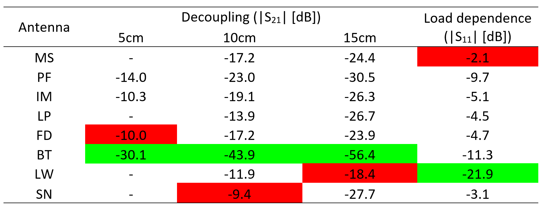
In figure 3 and figure 4 the power and SAR efficiency of the 8 antennas are visualized for the center and off-center line plots. These demonstrate highest power efficiency for the BT and LP concepts, and LP as well as PF show best SAR efficiency. When comparing the center and off-center plots the LP and MS concepts show the lowest decrease along the antenna while LP shows the strongest decrease along the line plot. The lowest decrease along the line plot is observed for the LW antenna.The decoupling simulation revealed the strongest intrinsic decoupling for the BT concept. The weakest intrinsic decoupling varies for the three distances (figure 5). Additionally, with increasing distance decoupling of some antennas increases steeper (LP, SN) than for others (FD, MS). Furthermore, at 5cm the MS, LP, LW, and SN concepts cannot be evaluated due to geometric restrictions. Lowest load dependence is found for the LW concept and the MS concept yielded highest load dependence (figure 5).
Discussion & Conclusion
This work demonstrates the value of a standardized protocol for the assessment of the transmission performance of RF building blocks. It provides valuable information for the design of RF arrays tailored to specific use-cases. For a SAR sensitive application SAR efficiency is of highest priority, which makes the PF or LP concepts suitable candidates for the assembly of a Tx array. For high density Tx arrays the BT concept bodes well with the need of high intrinsic decoupling. If the application is associated with a wide range of loadings the BT or LW concept provide a viable solution for a Tx array. If the application requires large volume coverage MS, LP, or SN concepts are advantageous.Since this abstract is intended to initiate a process of standardization, it covers only one setup for transmit antennas at 7T using the four proposed benchmarks. Thus, a further discourse on the used metrics and the selected setup to reach consensus on the settings of the standardized protocol is essential. Additional setups to collect data for different geometries, antenna concept's pTx capability, additional field strengths and the signal reception performance including the metric ultimate intrinsic SNR (UISNR)12 should also be assessed within later protocols.
To conclude, this work provides the first technical foundation for a standardized protocol for Tx analysis of RF antenna concepts and is based on FAIR principles. Our call for standardization and harmonization will benefit the MR imaging and engineering communities to streamline and tailor RF antenna developments.
Acknowledgements
This project has received funding from the European Research Council (ERC) under the European Union's Horizon 2020 research and innovation program under grant agreement No 743077 (ThermalMR) and the European Regional Development Fund under the operation number ‘’ZS/2019/02/97145‘‘.
References
1. Hernandez, Daniel; Kim, Kyoung-Nam (2020): A Review on the RF Coil Designs and Trends for Ultra High Field Magnetic Resonance Imaging. In: Investigative Magnetic Resonance Imaging 24, S. 95. DOI: 10.13104/imri.2020.24.3.95.
2. Kraff, Oliver; Quick, Harald H. (2019): Radiofrequency Coils for 7 Tesla MRI. In: Topics in magnetic resonance imaging: TMRI 28 (3), S. 145–158. DOI: 10.1097/RMR.0000000000000206.
3. Rietsch, Stefan H. G.; Quick, Harald H.; Orzada, Stephan (2015): Impact of different meander sizes on the RF transmit performance and coupling of microstrip line elements at 7 T. In: Medical physics 42 (8), S. 4542–4552. DOI: 10.1118/1.4923177.
4. Zivkovic, Irena; Castro, Catalina Arteaga de; Webb, Andrew (2019): Design and characterization of an eight-element passively fed meander-dipole array with improved specific absorption rate efficiency for 7 T body imaging. In: NMR in biomedicine 32 (8), e4106. DOI: 10.1002/nbm.4106.
5. Li, Mingyan; Jin, Jin; Weber, Ewald; Engstrom, Craig; Destruel, Aurelien; Crozier, Stuart; Liu, Feng (2022): Prostate imaging with Integrated Multi-modal Antenna with coupled Radiating dipoles (I-MARS) at 7T. In: International Society of Magnetic Resonance in Medicine, Article 3228.
6. Raaijmakers, Alexander J. E.; Italiaander, Michel; Voogt, Ingmar J.; Luijten, Peter R.; Hoogduin, Johannes M.; Klomp, Dennis W. J.; van den Berg, Cornelis A T (2016): The fractionated dipole antenna: A new antenna for body imaging at 7 Tesla. In: Magnetic Resonance in Medicine 75 (3), S. 1366–1374. DOI: 10.1002/mrm.25596.
7. Eigentler, Thomas Wilhelm; Winter, Lukas; Han, Haopeng; Oberacker, Eva; Kuehne, Andre; Waiczies, Helmar et al. (2020): Wideband Self-Grounded Bow-Tie Antenna for Thermal MR. In: NMR in biomedicine 33 (5), e4274. DOI: 10.1002/nbm.4274.
8. Solomakha, Georgiy; Svejda, Jan; Rennings, Andreas; Erni, Daniel (2020): A new RF coil for UHF MRI based on a slotted microstrip line. In: Journal of Physics Conference Series 1461, p 1-3. DOI: 10.1088/1742-6596/1461/1/012168.
9. Steensma, Bart; van de Moortele, Pierre-Francois; Ertürk, Arcan; Grant, Andrea; Adriany, Gregor; Luijten, Peter et al. (2020): Introduction of the snake antenna array: Geometry optimization of a sinusoidal dipole antenna for 10.5T body imaging with lower peak SAR. In: Magnetic Resonance in Medicine 84 (5), S. 2885–2896. DOI: 10.1002/mrm.28297.
10. Chen, Zhichao; Solbach, Klaus; Erni, Daniel; Rennings, Andreas (2016): Field Distribution and Coupling Investigation of an 8-Channel RF Coil Consisting of Different Dipole Coil Elements for 7-Tesla MRI. In: IEEE transactions on bio-medical engineering 64. DOI: 10.1109/TBME.2016.2602441.
11. Roemer, P. B.; Edelstein, W. A.; Hayes, C. E.; Souza, S. P.; Mueller, O. M. (1990): The NMR phased array. In: Magnetic Resonance in Medicine 16 (2), S. 192–225. DOI: 10.1002/mrm.1910160203.
12. Lattanzi, Riccardo; Wiggins, Graham C.; Zhang, Bei; Duan, Qi; Brown, Ryan; Sodickson, Daniel K. (2018): Approaching ultimate intrinsic signal-to-noise ratio with loop and dipole antennas. In: Magnetic Resonance in Medicine 79 (3), S. 1789–1803. DOI: 10.1002/mrm.26803.
Figures