4238
Improved Transmit Efficiency and Clinical Coverage using a Cervical Spine Array with a Volumetric Transmitter at 7T
Alexander Smerglia1, Labros Petropoulos1, Jami Tatulinski1, Tsinghua Zheng1, Xiaoyu Yang1, Jagjit Sidhu2, Ken Sakaie2, and Mark Lowe2
1Quality Electrodynamics (QED), Mayfield, OH, United States, 2Imaging Institute, Cleveland Clinic, Cleveland, OH, United States
1Quality Electrodynamics (QED), Mayfield, OH, United States, 2Imaging Institute, Cleveland Clinic, Cleveland, OH, United States
Synopsis
Keywords: High-Field MRI, Brain, Spine, Imaging, Cerebellum
Several challenges are present when imaging the cervical spine in high-field MRI, such as achieving B1 coverage over the desired anatomy while maximizing efficiency of the transmitter. A cervical spine array coil with a volume transmit birdcage was built and tested on a system for improved transmit coverage and efficiency over previous prototypes. The coil consists of a partially shielded 22-rung birdcage transmitter and a 24 element receive RF array. A new mechanical design with larger eye windows improves the clinical experience. Improved transmit efficiency and complete B1 field coverage in the cervical spine region were confirmed through volunteer imaging.Introduction
Imaging the cervical spine region at ultra-high field strength has proved difficult due to the unique shape of the anatomy in the region [1]. Previously, a cervical spine coil that imaged down to the C4-C6 region was built and tested [2]. However, the coil exhibited some signal degradation at C6 compared to higher regions of the spine due to insufficient receive array coverage and required a high transmit voltage to achieve the optimal B1 flip angle. To achieve a more uniform transmit excitation in the cervical spine region, especially the lower region (C5-C7), a birdcage transmit coil with redesigned geometry and receive array with additional elements were constructed. The new transmit design increased the rungs on the birdcage from 16 rungs on the previous build to 22 rungs in order to improve the transmit efficiency by lowering radiation loss. Better efficiency lowers the transmit voltage needed from the system to achieve optimal B1 excitation, which in turn lowers SAR levels while imaging and allows the user to image the relevant anatomy at higher resolution. Additionally, the size and curvature of the mechanical design, along with sizeable eye windows, allows for a clinically viable experience.Method
The birdcage transmitter was designed with a unique shape (shown in Fig. 1) in order to curve around the patient shoulder and reach lower on the neck region. The birdcage is 27.4cm in diameter and surrounded by a partial RF shield 31.4cm in diameter, meaning there is 2.0cm separation between birdcage and shield. The height of the birdcage 27.5cm in the tallest region, which is increased from 23.5cm in the previously built C-spine coil in order to increase B1 excitation coverage. The birdcage length shortened to 19.6cm at the center of the shoulder cutout region, which is reduced from the 20.7cm of the previous build due to the more extreme shape of the shoulder cutout. This structure was confirmed to produce a uniform B1 field in the lower region of the Tx structure through the use of XFdtd EM simulation software (Remcom Inc., State College, PA). The transmitter was constructed as a birdcage with 24 equally spaced rungs but with 2 of the rungs removed to allow room for eye windows (shown in fig. 2). The method of tuning a birdcage transmitter with missing rungs has been explored previously, and it has been shown the birdcage would produce a sufficiently uniform field [3]. The receive structure (shown in fig. 3) consists of a 24 element loop array, which was increased from 16 elements in the previous design. The number of elements in the columns of the posterior array have been increased in order to expand coverage in the S-I direction. There were additional elements added to the anterior side to increase signal quality in the anterior region of the spinal column. Columns of receive elements were separated by gaps. Neighboring receive elements in each column were isolated via element overlap, and other neighbors were isolated by the use of low input impedance preamplifiers [4]. The mechanical design, found in fig. 4, consists of split anterior and posterior sections with curvature for patient comfort and positioning. The width and anterior-to-posterior height of the patient head/neck opening are 21.5cm and 26.2cm, respectively. These sizes were chosen such that 99 percent of the population could comfortably place their head and neck in the coil. The eye windows, which have been increased from two to four, are much wider than in previous builds, further improve patient comfort during scanning.Results
The coil was tested on a Siemens Terra 7T MRI (Siemens Healthineers, Erlangen). A healthy volunteer was imaged under an IRB-approved protocol with a Turbo Spine Echo sequence. Figure 5 shows a sagittal image of the cervical spine area, including all vertebrae C1-C7. The transmitter produced satisfactory B1 field uniformity in the region. Furthermore, the B1 excitation region reached the top thoracic vertebra, T1, though with somewhat weaker signal strength. This exhibits greater coverage than the previous build which imaged down to C6, with the signal at C6 somewhat weaker than that of C5 and above. The system transmit voltage required for optimal SNR was 310V for this patient and protocol, a greater than 20% improvement over a previous C-Spine build [2].Conclusion
A new cervical spine coil was constructed and performance evaluated on a 7T system. The overall mechanical design and eye windows improve patient comfort in a clinical setting. The 22-rung birdcage transmitter produced a uniform B1 field with greater coverage and improved efficiency in comparison to previously constructed coils. An increase receive channel count also helps to expand the imaging coverage. The coil allows for imaging of the entire region of the cervical spine, and with greater resolution than previously possible.Acknowledgements
No acknowledgement found.References
[1] R. Barry, et al., “Spinal Cord MRI at 7T”, Neuroimage. 2018 March; 168: 437-451. Doi:10.1016/j.neuroimage.2017.07.003
[2] T. Zheng, et al., “A Cervical Spine Array Coil with Volume Transmitter at 7 Tesla”, Proc. Intl. Soc. Mag. Reson. Med. 24, 2144 (2016)
[3] T. Zheng, et al., “A Novel clinical Friendly 7T T/R 32-Channel Head Coil Using Skipped-Rung Birdcage as Transmitter” Proc. Intl. Soc. Mag. Reson. Med. 28, 6283 (2020)
[4] H. Fujita, et al., “A 3T Head Transmitter Integrated with 3D Parallel Imaging Capable 16-Channel Receive Array Coil”, in Proc. Intl. Soc. Mag. Reson. Med. 15, 3254 (2007)
Figures
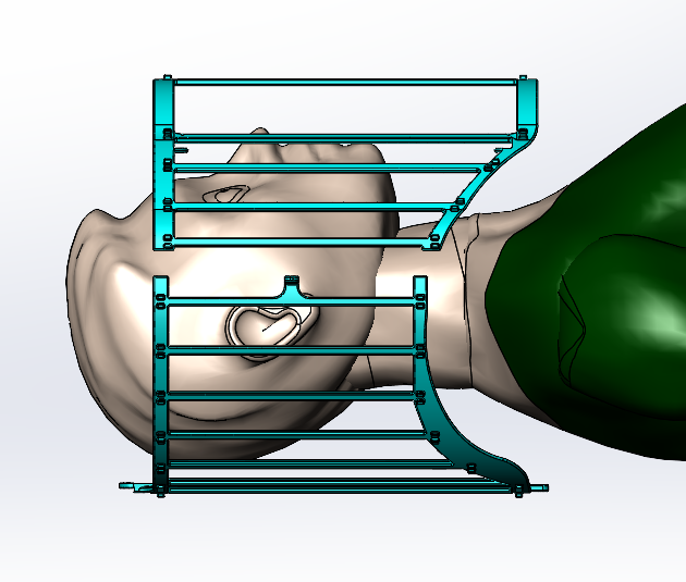
Figure 1: Birdcage transmit coil with shoulders cut out
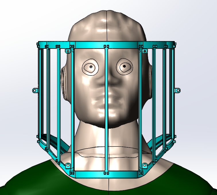
Figure 2:
Birdcage transmit coil with two rungs removed over patient eyes
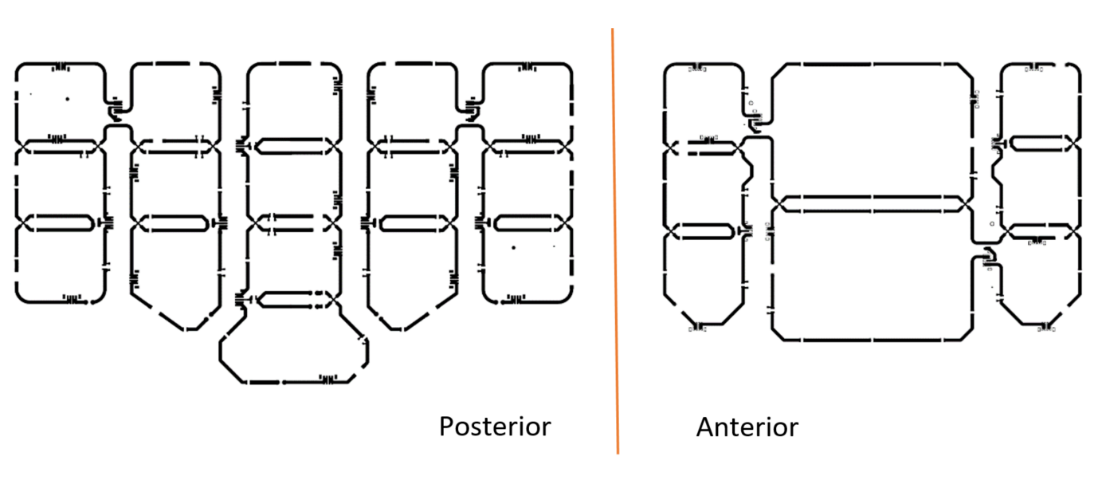
Figure 3: Posterior
(Left) and Anterior (Right) Receive Artwork Element Layout
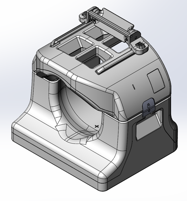
Figure 4: Mechanical
design of the coil
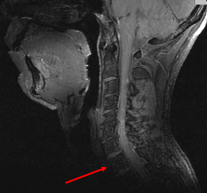
Figure 5: Sagittal
image of the entire cervical spine. T1 vertebra is indicated by the arrow
DOI: https://doi.org/10.58530/2023/4238