4237
Lumped inductors in RF resonators decrease the B1 fields in samples at ultrahigh fields
Yunkun Zhao1 and Xiaoliang Zhang1
1Biomedical Engineering, State University of New York at Buffalo, Buffalo, NY, United States
1Biomedical Engineering, State University of New York at Buffalo, Buffalo, NY, United States
Synopsis
Keywords: High-Field MRI, RF Arrays & Systems
This study investigates the effect of lumped inductors used in RF resonant circuits on the magnetic field strength generated by the radiofrequency (RF) coils. The results show that the lumped inductors can reduce B1 fields in samples.Introduction
Radiofrequency coil array plays an essential role in MR signal excitation and reception. Multichannel MRI systems require an RF coil array to increase image quality in terms of SNR and image speed. One key obstacle in RF coil array design is the electromagnetically coupling between coil elements of the RF array. In order to address this issue, lumped inductors are often used in the decoupling circuits or in coil’s resonant circuit. In some occasions, the lumped inductors are also used to tune the coil, either array or non-array, to the desired frequency [1]. Inductor is a device which stores magnetic fields. Due to the confined area of a lumped inductor, the magnetic field stored in the lumped inductor may not be “seen” by the imaging sample or subject, potentially resulting in reduced B1 fields in the sample and thus reducing the detection sensitivity. In this study, we investigate how magnetic field strength will change with the inductance of the lumped inductors used in the RF coil circuit.Methods
The coil used in this study is shown in Fig.1. We designed a 10×10 cm2 LC loop coil with 2 capacitors and a lumped inductor. A phantom (imaging sample) positioned 10mm above the coil has a size of 50mm in height and75mm in width. Length of the phantom is defined as an imaging area, which reflects the position of the imaging object in real applications. The LC loop coil was built with 6.35mm width copper tape, and the lumped inductor in the solenoid shape was built with 16 AWG copper wire. The length of the lumped inductor is 10mm, and the outer radius of the inductor is 1.25mm. These dimensions remained the same throughout the experiment. The inductance value changes by increasing or decreasing the turns of the solenoid inductor. There are 7 cases been tested: 4 turns (9nH inductance), 5 turns (14nH inductance), 8 turns (35nH inductance), 10 turns (55nH inductance), 16 turns (142nH inductance), 20 turns (221nH inductance). No lumped inductor in the circuit is defined as 0nH. The coils in every case were tuned to 298MHz (the Larmor Frequency of proton 1H at 7T) using tuning capacitors. Numerical results of the proposed designs are obtained using electromagnetic simulation software CST Studio Suite (Dassault Systèmes, Paris, France). The performance of the coils was evaluated by a 2D B1 field distribution plot and a 1D plot of magnetic field strength inside the imaging area or sample. All the results were normalized to the input power at the resonant frequency with 0.5Watt total power from the power source.Results
Fig.2 shows the B1 field distribution at all different inductance values. Calculated field distribution results show that B1 field around LC loop coil in the transverse plane decreases with the increase in inductance of the lumped inductor. Fig.3 demonstrates the 1D profile of the B1 fields in two different orientations. Both 1D plots in Fig. 3 further indicate the B1 field reduction with increase in lumped inductance. Fig.4 shows the B1 field distribution at different inductance values in the imaging sample. The result indicates the same magnetic field strength changing pattern in Fig.2, in which the field strength decreases and shifts to the right side. Fig.5 shows the average magnetic field strength plot in the imaging area, and the step size of the data point is 0.25mm. The result reveals that when using a lumped inductor with 221nH inductance, the average field strength decreased by 62% compared with a coil with no lumped inductor.Conclusion
In this study, we investigate the effect of the lumped inductor on the magnetic field strength of an RF coil. Results show that the use of lumped inductor in resonant circuit would negatively impact the B1 field in the sample, ultimately degrading the MR imaging sensitivity.Acknowledgements
This work is supported in part by the NIH under a BRP grant U01 EB023829 and by State University of New York (SUNY) under SUNY Empire Innovation Professorship Award.References
1. Yan X, Gore J C, Grissom W A. Self-decoupled radiofrequency coils for magnetic resonance imaging[J]. Nature communications, 2018, 9(1): 1-12.Figures
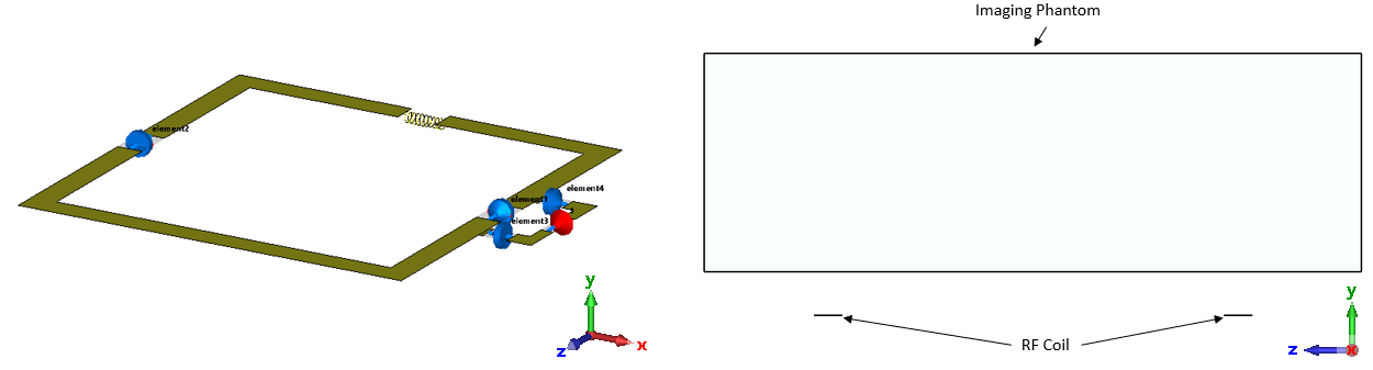
Fig.1. LC loop coil and imaging area setup. The left inset shows the
structure for circuit with a lumped inductor in the resonant circuit. The right
inset shows the sample geometry and its relative position to the coil.
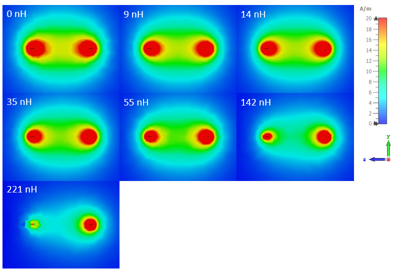
Fig.2. B1
field distributions of a loop surface coil at different inductance values of a
lumped inductor.
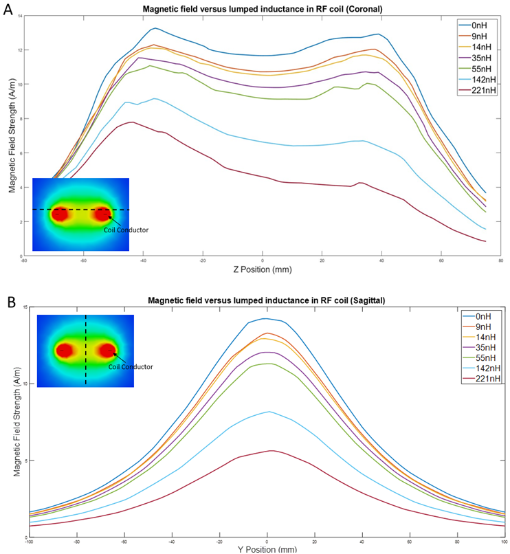
Fig.3. 1D profiles of B1 field strength along the dash line indicated in
upper-left inset for each inductance value.
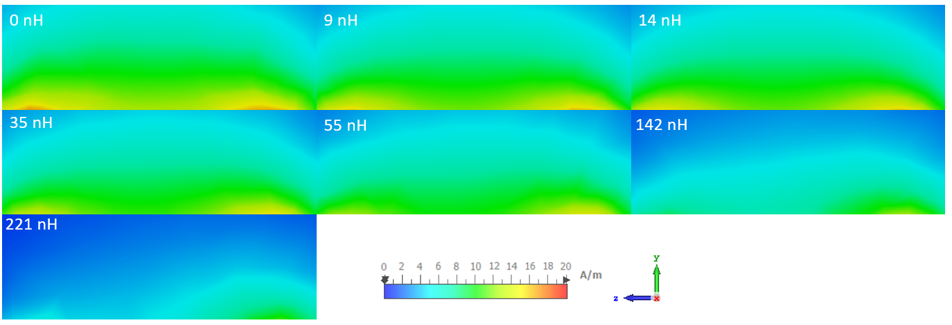
Fig.4. B1
field distributions in the sample (in y-z plane at x=0) at different inductance
of the lumped inductor
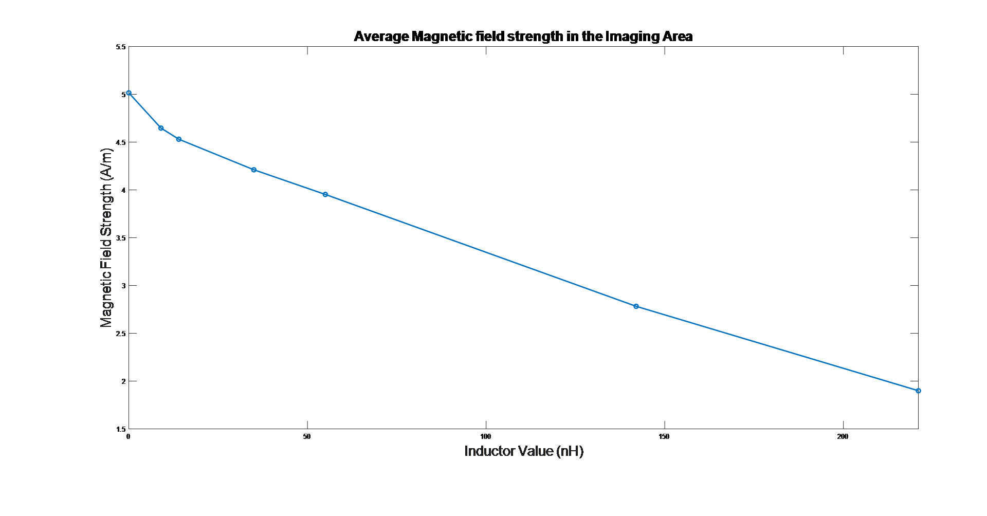
Fig.5. Plot of average magnetic field
strength in the sample at different inductance value of the lumped inductor.
DOI: https://doi.org/10.58530/2023/4237