4236
Development of Head and C-Spine coils for use at 7T1Cleveland Clinic, Cleveland, OH, United States, 2Quality Electrodynamics, Mayfield Heights, OH, United States
Synopsis
Keywords: High-Field MRI, Spinal Cord
MR imaging at 7T provides a greater signal intensity, which yields some combination of a greater signal-to-noise ratio, smaller voxel size, and/or faster scan times compared with lower field strengths. However, there remains room for improvement at 7T in terms of image homogeneity and a limited selection of coils. In this work, we summarize ongoing efforts to develop a single-transmit (STX) cervical spine (C-spine) and a parallel transmit (PTX) head coil. Both coils have a more open design with detachable anterior halves and larger physical dimensions.Introduction
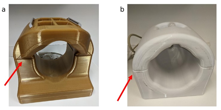
MR imaging at 7T provides a greater signal intensity, as compared with lower field strengths, yielding some combination of a greater signal-to-noise ratio, smaller voxel size, and/or faster scan times compared with lower field strengths 1. However, there is a limited selection of coils 2 at 7T. Tight-fitting coils are optimized for SNR, particularly at cortex, and are ideal for research studies. However, such coils may be inappropriate in a clinical setting, as some patients may not be able to fit in the coil comfortably or at all. In this work, we summarize ongoing efforts to develop a single-transmit (STX) cervical spine (C-spine) and a parallel transmit (PTX) head coil 3. The coils examined here are designed to accomodate 99% of patients 4. Both are split-coil design, which facilitates patient handling and comfort.Methods
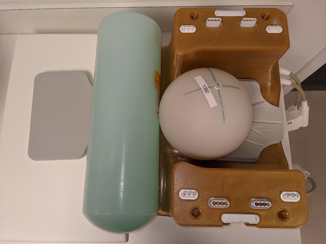
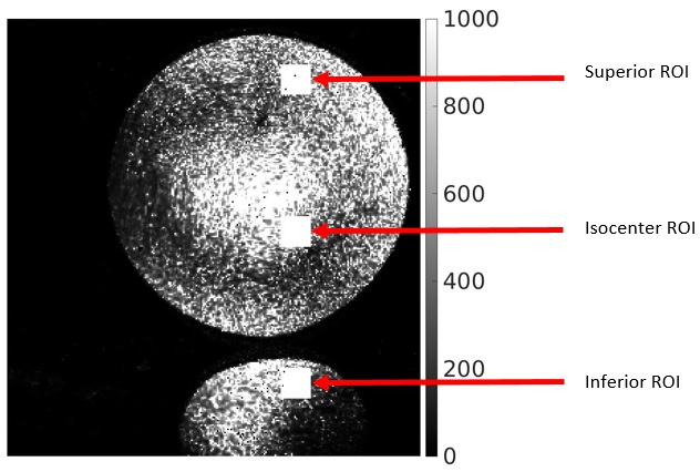
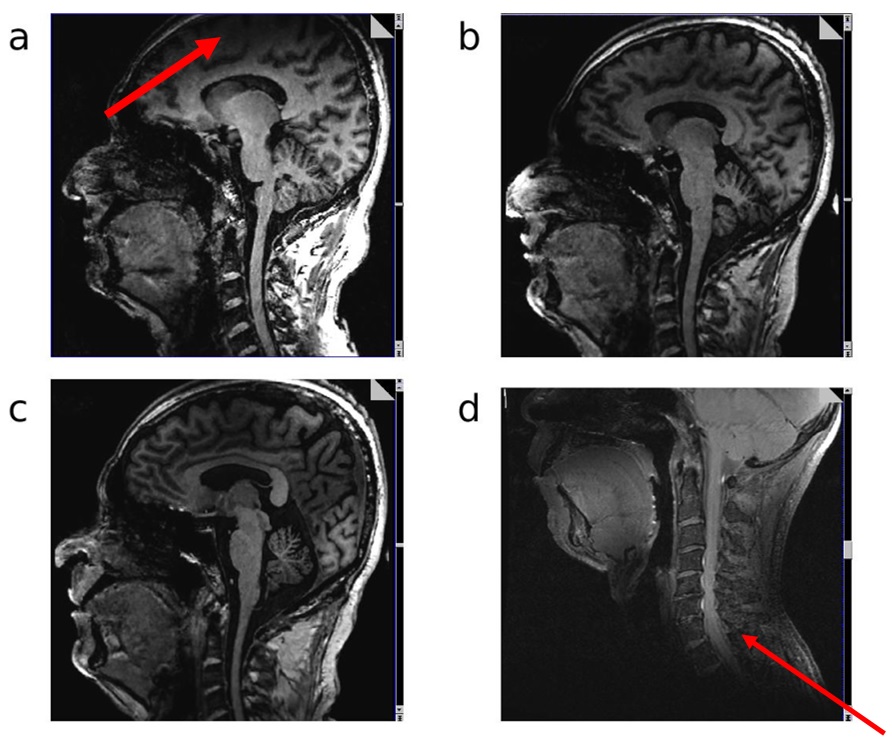
Imaging was performed on a Siemens 7T Magnetom Terra (Siemens Healthineers, Erlangen, Germany) with a C-Spine 24RX/1Tx coil and a Head coil 32RX/8Tx (Figure 1). For the PTX head coil, the same imaging was performed with and without B1 shimming, in which case the coil acts similarly to an STX coil. Large FOV MP2RAGE acquisitions were acquired to image the top of the brain and the C-spine in one image (sagittal, 288 mm x 272 mm FOV, 240 x 227 matrix, 224 slices 0.83 mm thick, TE/TR=2.9/6000 msec, compressed sensing undersampling factor 10 and 240 Hz/Pixel bandwidth). Imaging was performed on one subject under an IRB-approved protocol. Additional MP2RAGE scans with phantoms (Figure 2) were acquired to measure SNR. SNR was calculated using the voxel mean and standard deviation of three separate acquisitions. The mean of three 20x20 regions were then calculated to provide a measure of the SNR near the top, middle and bottom of the phantom in the inferior-superior direction (Figure 3). Finally, a T1 TSE (sagittal, 230 mm x 230 mm, 256 x 320 matrix, 17 slices 3 mm thick, TE/TR = 9.2/704 ms and 260 Hz/pixel bandwidth) scan, that was originally setup for C-Spine imaging, was acquired showing the true coverage of the C-Spine coil.Results and Discussion
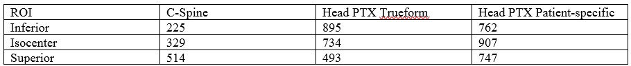
In Figure 3, we show the results of a slice at the same location on both coils. The spinal cord shows good delineation through C5 on both coils. It is possible to image even lower, especially on the C-Spine coil (Figure 3d), where this coil performs best. This performance advantage may prove advantageous when grading spinal cord lesions and atrophy in multiple sclerosis 5,6. However, the C-Spine coil experiences significant dropoff above the middle region of the brain. In Figure 5, we show the ROIs used for calculating SNR. Table 1 summarizes the values of SNR.Conclusion
The coils examined here provide new options for imaging of C-spine and at PTX. Both are split coils with large inner diameters 4, which are important for use in a clinical setting. The split coil design also has advantages with regard to claustrophobia. These coils thus add flexibility to head and c-spine imaging while maintaining image quality at a comparable level to what is commercially available . The extra flexibility afforded by these coils will contribute to the utility of UHF imaging in a clinical setting.Acknowledgements
We thank Tobias Kober and Tom Hilbert of Siemens Healthineers for use of WIP 925b. We thank the Imaging Institute at the Cleveland Clinic for funding support.References
1. Brown, R. W., Cheng, Y.-C. N., Haacke, E. M., Thompson, M. R., & Venkatesan, R. (Eds.). (2014). Magnetic Resonance Imaging. John Wiley & Sons Ltd.
2. Jones SE, Lee J, Law M. Neuroimaging at 3T vs 7T: Is It Really Worth It? Magn Reson Imaging Clin N Am. 2021 Feb;29(1):1-12. doi: 10.1016/j.mric.2020.09.001. PMID: 33237010.
3. Padormo F, Beqiri A, Hajnal JV, Malik SJ. Parallel transmission for ultrahigh-field imaging. NMR Biomed. 2016 Sep;29(9):1145-61. doi: 10.1002/nbm.3313. Epub 2015 May 19. PMID: 25989904; PMCID: PMC4995736.
4. 99% human male head size, SOLIDWORKS.
5. Lublin FD, Reingold SC, Cohen JA et al. Defining the clinical course of multiple sclerosis: the 2013 revisions. Neurology. 2014 Jul 15;83(3):278-86. doi: 10.1212/WNL.0000000000000560. Epub 2014 May 28. PMID: 24871874; PMCID: PMC4117366.
6. Oh J, Ontaneda D, Azevedo C et al., Imaging outcome measures of neuroprotection and repair in MS: A consensus statement from NAIMS, Neurology Mar 2019, 92 (11) 519-533; doi: 10.1212/WNL.0000000000007099
Figures