4232
Effect of conductor width on coil array coupling
Yunkun Zhao1 and Xiaoliang Zhang1
1Biomedical Engineering, State University of New York at Buffalo, Buffalo, NY, United States
1Biomedical Engineering, State University of New York at Buffalo, Buffalo, NY, United States
Synopsis
Keywords: High-Field MRI, Non-Array RF Coils, Antennas & Waveguides
This study investigates the effect of conductor width of the RF coils to the EM coupling of an array. The results show that the wide conductor of the RF coils offers less EM coupling among resonant elements.Introduction
A significant challenge in the design of the RF receiver or transceiver arrays is the electromagnetic (EM) coupling between RF coil elements of an array [1]. The EM coupling between array elements is complicated and is related to many factors, including array layout, coil geometry, coil material, and the resonant frequency. In this work, we investigate how the coil conductor geometry or width influences the decoupling performance.Methods
The coil array we used for investigation is designed on a 2-dimensional plane, as shown in Fig.1. The conductor used for the circuit construction is a copper tape assigned the exact specification with annealed copper. The size of the LC circuit coil is 8×8 cm2, including two tuning capacitors, and has been tuned to have a 300MHz resonant frequency. Two coils in the array are identical, but only one has a power supply and matching circuit, which include two matching capacitors. As shown in Fig. 2, the width of the copper tape changes from 5mm to 30mm during the research and the width of the coil and the gap between coils remain unchanged. The value of the tuning capacitor and matching capacitor will also change to remain at the resonant frequency of the single coil at 300MHz. Numerical results of the proposed designs are obtained using electromagnetic simulation software CST Studio Suite (Dassault Systèmes, Paris, France). Because of the principle of inductive coupling, two resonant frequencies will appear on the scattering parameters after the simulation. The performance of the coil array in coupling was evaluated by scattering parameters and the coupling coefficient of resonators which were calculated from two resonant frequencies after coupling. The definition of the coupling coefficient of two coupled resonators is k = (fo2-fe2)/(fo2+fe2), k is the coupling coefficient, fo is the first resonant frequency, and fe is the second resonant frequency [2].Results
Fig.3 shows the scattering parameters for the 10mm copper tape width case as an example of scattering parameters after inductive coupling. Fig.4 shows the coupling coefficient of resonators versus the width of the copper tape result. The coupling coefficient shows that while the width of the copper tape increases, the coupling strength between coils will decrease. The relationship between the coupling coefficient and the copper tape width can be approximated as function: f(x) = 0.1002+0.005381×cos(0.04304x)+0.07985×sin(0.04304x). The reason for this phenomenon is that even though increasing the copper tape width will reduce the inductance of the coil, and the copper tape will block the flow of the magnetic flux. Because magnetic flux closer to the coil is always stronger, the increasing width of copper tape blocks the flow of magnetic flux and reduces the induced electromotive force. Therefore, the coupling strength between two coils also decreases.Conclusion
This study investigates the relationship between conductor width and coupling coefficient. The results show that EM decoupling improves with the increase in width of the coil conductor in the case of loop type coils. This result may lead to potential decoupling techniques using resonators.Acknowledgements
This work is supported in part by the NIH under a BRP grant U01 EB023829 and by State University of New York (SUNY) under SUNY Empire Innovation Professorship Award.References
1. Roemer PB, Edelstein WA, Hayes CE, Souza SP, Mueller OM. The NMR phased array. Magn Reson Med. 1990 Nov;16(2):192-225. doi: 10.1002/mrm.1910160203. PMID: 2266841.
2. Tyurnev V V, Belyaev B A. Interaction of parallel microstrip resonators[J]. Elektronnaya tekhnika. Ser. Elektronika SVCh, 1990 (4): 25-30.
Figures
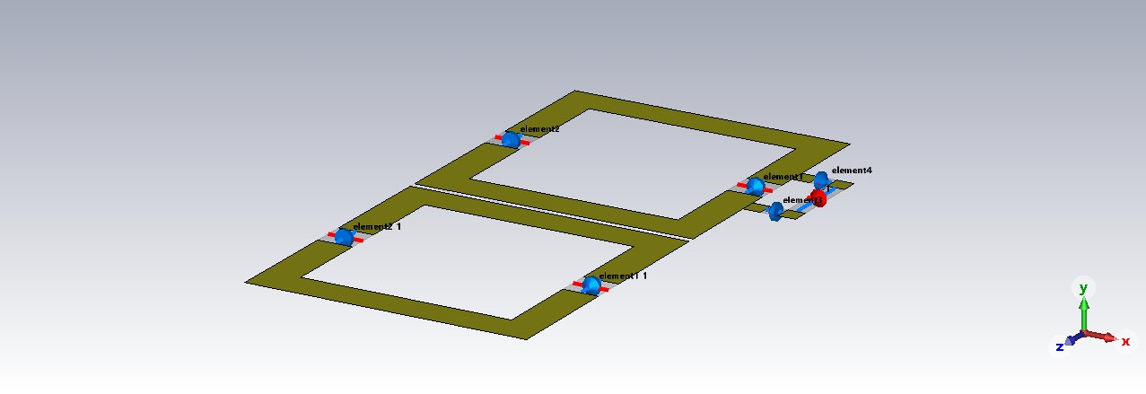
Fig. 1. LC coil
array setup. The figure shows the structure for 10mm width copper tape.
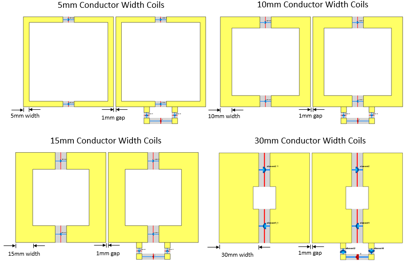
Fig. 2. The width of
the conductor increases during the research. Size of coils and gap between them
does not change.
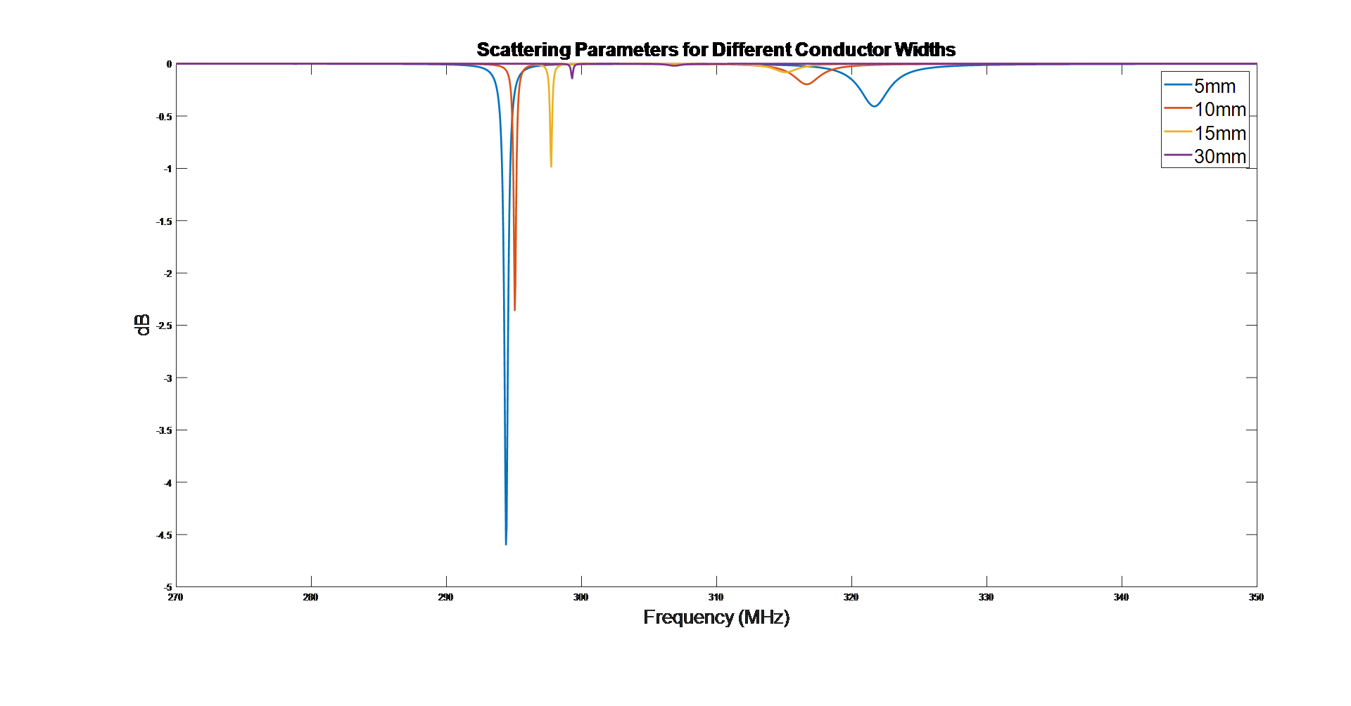
Fig. 3. Scattering
parameters of two coupled 5mm, 10mm, 15mm, and 30mm width copper tape.
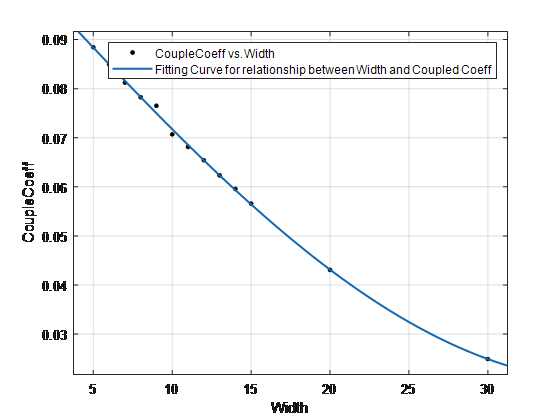
Fig. 4. Coupling coefficient versus
copper tape width and the fitting curve for the data.
DOI: https://doi.org/10.58530/2023/4232