4086
Exploration of the shielded-coaxial-cable coil as transceive array element for 9.4T MRI1Department of Electrical Engineering, Technical University of Eindhoven, Eindhoven, Netherlands
Synopsis
Keywords: High-Field MRI, High-Field MRI, RF arrays, transcieve coils, SCC coil
The recently proposed shielded-coaxial-cable (SCC) coils are intrinsically highly decoupled elements. Their suitability in multichannel transceiver arrays at ultra-high field was successfully demonstrated in 7T arrays. In this work, we investigated the single element and array properties of SCC coils at 9.4T. We simulated the SCC element and compared its properties (B1+, SAR) with those of a conventional loop coil. Subsequently, we fabricated eight SCC coils and investigated their coupling properties when placed in various configurations. SCCs at 400MHz provided similar B1+ and SAR efficiency, but generated ~25% less SAR10g,max . SCC performed well in different array configurations.Introduction
The design of multichannel arrays for operation at ultra-high field is challenging due to several aspects: interelement coupling must be low, efficiency must be high and the energy deposition should be low1,2. Recently, the shielded-coaxial-cable (SCC) coil was proven to be a suitable array element for 7T MRI3,4 (300MHz) due its flexibility, and low interelement coupling properties. When placed in an array configuration, the SCC coil showed a low sensitivity to various amount of overlap, bending and elongation4 at 300MHz. In this work, we investigate the use of SCC elements in multichannel flexible arrays for applications at 9.4T human MRI (400MHz).Methods
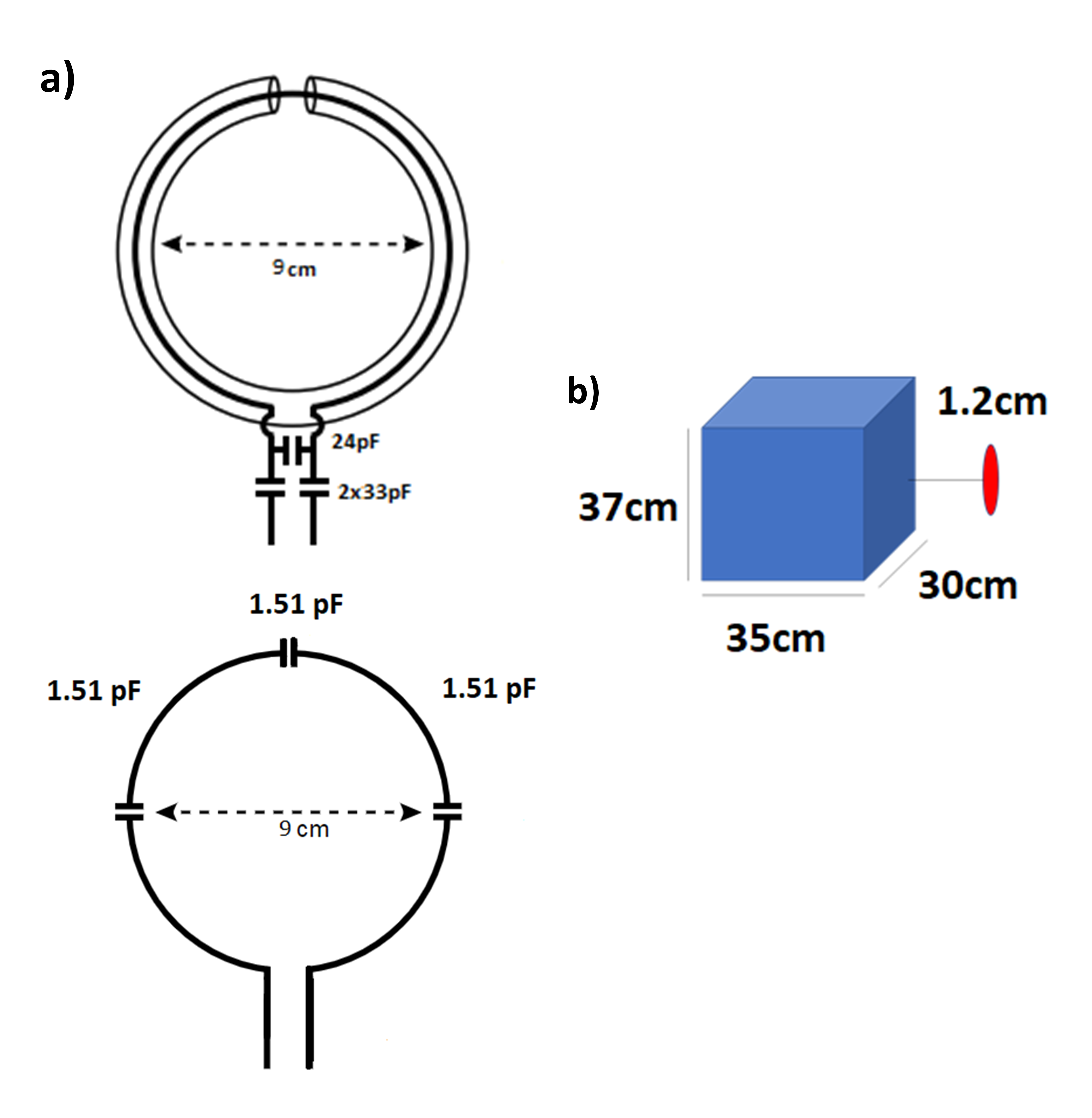
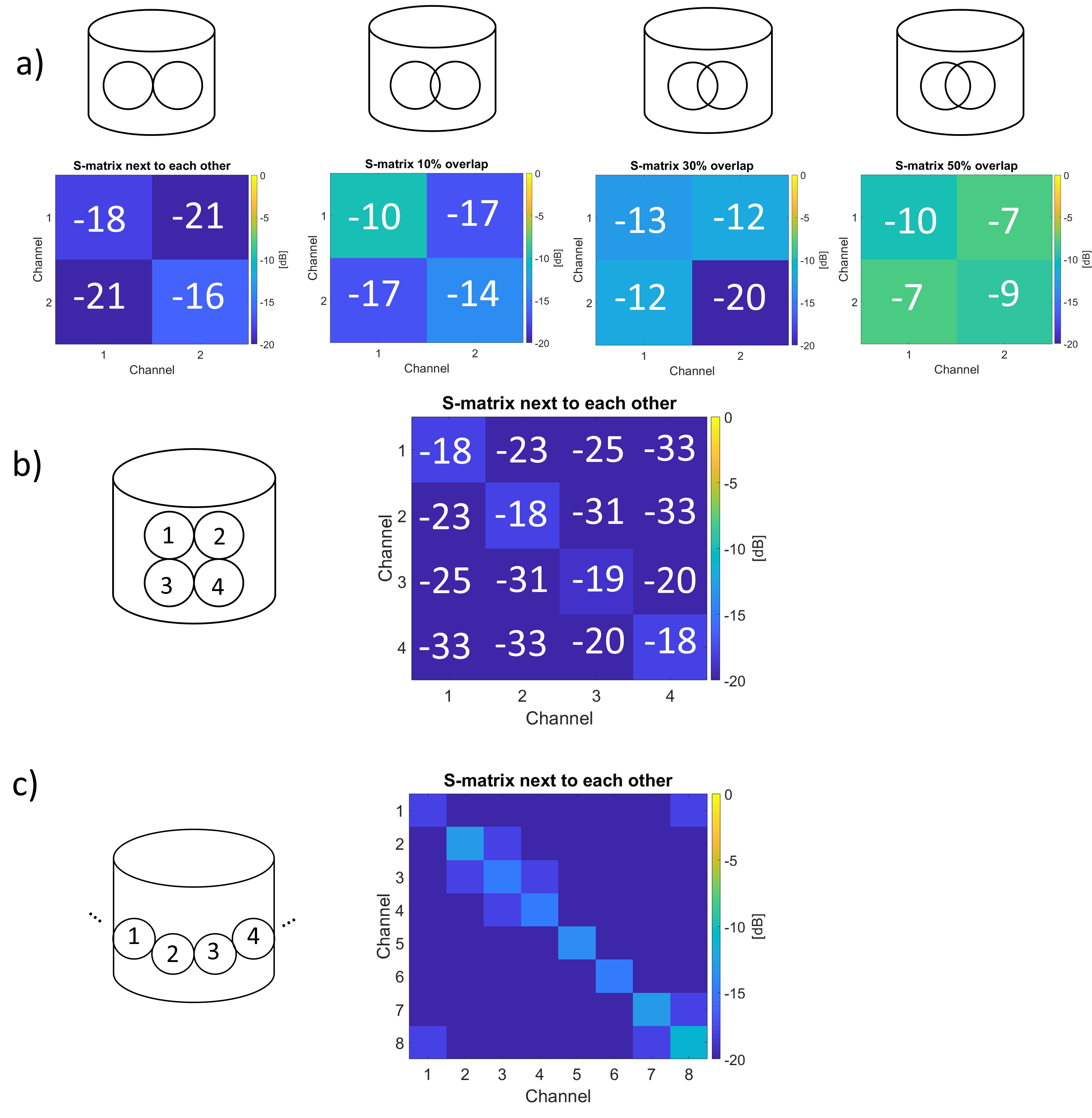
Eight identical SCC coils for operation at 400MHz were fabricated using a RG316 coaxial cable (2.45mm diameter). For SCC fabrication, we started from the design proposed for 7T imaging4 (300MHz). We tuned the resonant peak at 400MHz by shortening the cable length, and we matched the coils using two 33pF series capacitances and a 24pF parallel capacitance. The resulting coil diameter was ~9cm when full-opened (round coil), ~6.5cm when at rest (elongated). The SCC coils were placed on a cylindrical phantom (εr=60, σ=0.6 S/m, phantom diameter=18 cm), in a tight fit configuration (~7cm diameter per coil) and the distance between coils and phantom was 12mm. S-parameter measurements of the coils in various array configurations were performed using a VNA (N9914A FieldFox 6.5 GHz RF Analyzer). The array configurations were: (i) 2-coil array for different amount of overlap and distance between the elements (ii) 4-coil array in a 2x2 configuration, with adjacent coils (iii) full 8-element configuration around the phantom, with adjacent coils (figure 2). In all the configurations, the cables were routed to minimize coupling.We also compared SCC and conventional loop coils using simulations (CST Microwave Studio, Darmstadt, Germany). The SCC coil was modeled as coaxial cable RG316 (2.45mm diameter, Figure 1).
Results
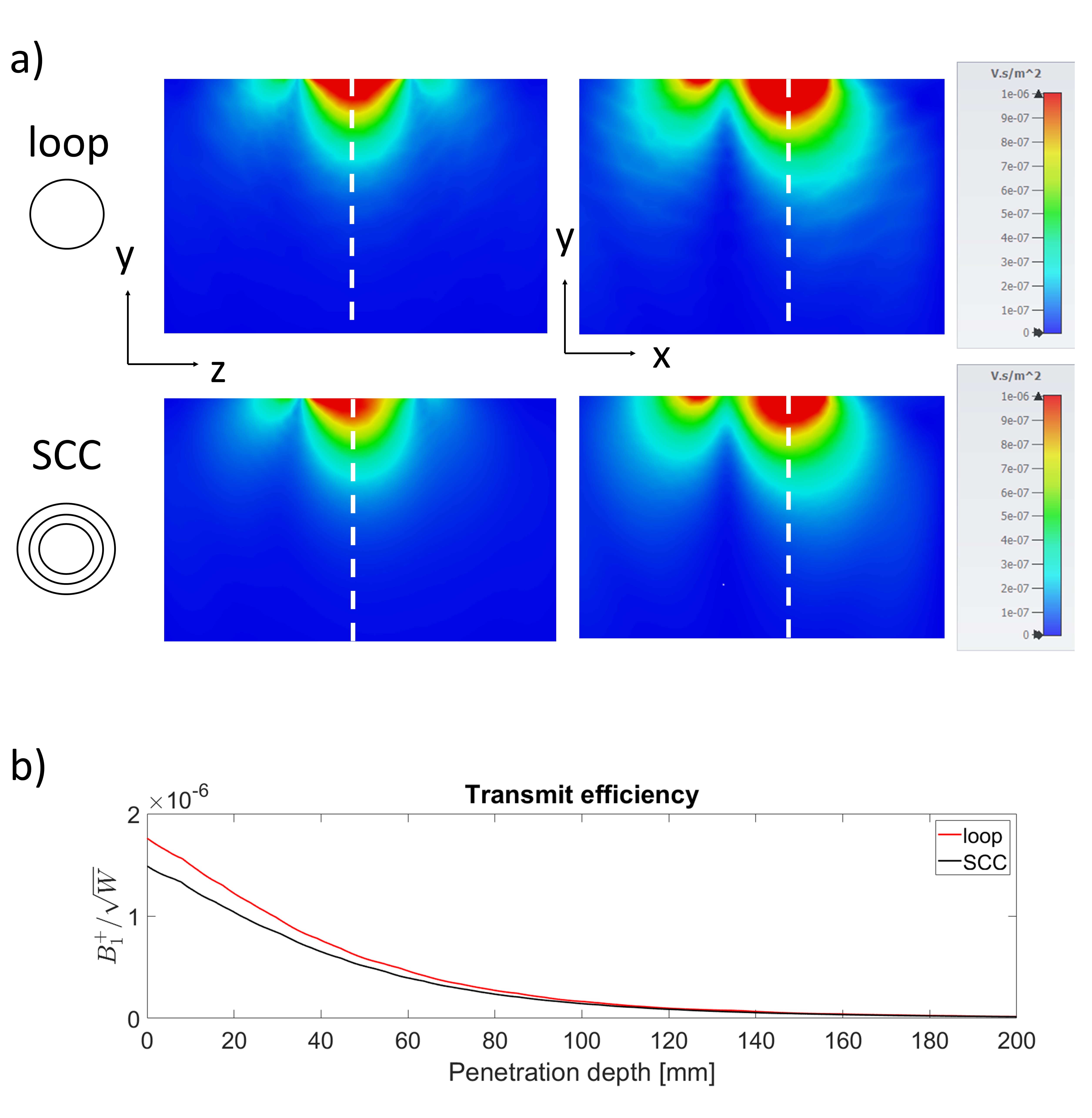
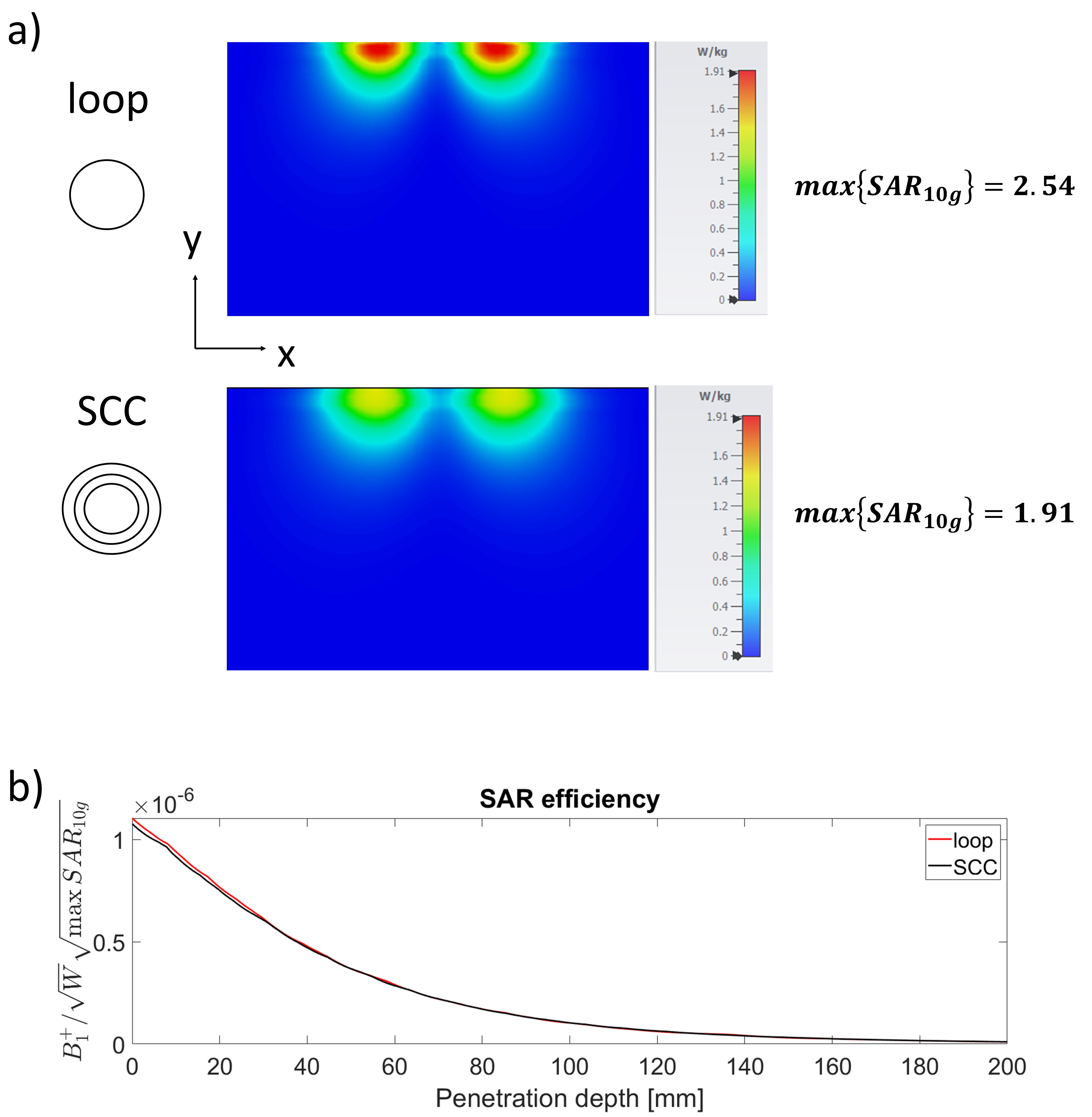
Figure 2 compares the results for the B1+ field maps and transmit efficiency of SCC and conventional coils.Figure 3 shows the results for the SAR10g,max and SAR efficiency. The SAR10g,max was 1.91 W/kg for an SCC and 2.54 W/kg for a conventional loop.
Figure 4 shows results of the measured S-parameters of different SCC array configurations on a cylindrical phantom. At any examined configuration – except when coils were 50% overlapped - The S11 and S21 parameters were below -10dB (S21< -15dB on average).
Discussion
As expected, the SCC coils designed for operation at 9.4T were of smaller diameter ( ~9cm diameter max aperture) than SCC coils designed for operation at 7T ( ~12.5cm diameter max aperture).While there were no significant differences in the B1+ field maps, in the transmit efficiency, and in the SAR efficiency, the SAR10g,max was ~25% higher in the loop case, and also the SAR field maps revealed higher energy deposition for loops. In array configurations, the fabricated SCC coils showed low interelement coupling when slightly overlapped, or next to each other. However, coupling was high in a 50% overlapped configuration. This effect was not observed in simulations – in which the PCB used to solder the tuning and matching circuit was not modelled - or at 300MHz.
Conclusions
In this study, we show that SCCs at 400MHz provide equal performance than capacitive segmented loops in terms of transmit efficiency, B1+ field maps and SAR efficiency, but generate ~25% less SAR10g,max . Measurements of the S-matrix reveal that the SCC are versatile elements, since the same design performs well in a large variety of array configurations. The observed decoupling properties of the coil make it suitable for use in tight fit array configurations. One of the intended applications will be c-spine spinal cord imaging at 9.4T - at the moment, there is no dedicated coil for this region5. SCC coil is also a suitable candidate for densely populated receive arrays at 9.4T.Acknowledgements
No acknowledgement found.References
1. P.B. Roemer et al. , “The NMR phased array”, in Magn. Reson. Med. (1990) 16:192–225.
2. Nikolai I. Avdievich et al. , “Decoupling of a double‐row 16‐element tight‐fit transceiver phased array for human whole‐brain imaging at 9.4 T”, NMR in Biomedicine. 2018;31:e3964
3. T. Ruytenberg et al., “A flexible five-channel shielded-coaxial-cable (SCC) transceive neck coil for high-resolution carotid imaging at 7T”, Magn. Reson. Med. (2020); 84:1672–1677
4. T. Ruytenberg et al., “Shielded-coaxial-cable Coils as Receive and ransceive Array Elements for 7T Human MRI.” Magn. Reson. Med. (2019) 83(3):1135–46.
5. O. Geldschläger et al. , “Ultrahigh-resolution quantitative spinal cord MRI at 9.4T”, Magn. Reson. Med. (2021); 85: 1013-1027
Figures