4084
Understanding Loss Mechanisms in Double-Tuned Body Coils To Improve B1 Efficiency
Busra Kahraman-Agir1, Dimitri Welting1, Mark Gosselink1, and Dennis Klomp1
1Department of Radiology, University Medical Center Utrecht, Utrecht, Netherlands
1Department of Radiology, University Medical Center Utrecht, Utrecht, Netherlands
Synopsis
Keywords: High-Field MRI, Non-Array RF Coils, Antennas & Waveguides, multinuclei body coils, double tuned
Double-tuned circuits are often comprised of internal resonances in tank circuits that locally may amplify RF currents and thereby cause extra loss compared to single tuned RF coils. Here, we investigated the loss mechanisms of RF borecoils for the operating frequencies of 120.68, 78.8 and 45.8MHz for the purpose to design a B1+ efficient multi-tuned RF borecoil for metabolic MRI of 2H, 23Na and 31P, respectively at 7T.
Introduction
Determining the source of the loss in an RF transmit coil is crucial since the loss directly has an effect on B1+ field of the coil and cost of the RF amplifier. Particularly transmit body coils are susceptible to the loss due to their large excitation volume. Moreover, for nuclei other than 1H, often RF amplifiers are available at much lower power, thereby requiring to severely increase the RF pulse duration (which jeopardizes SNR in the short T2 of 23Na spins) and thus limiting the excitation bandwidth which may be insufficient to excite the full chemical shift dispersion of for instance 31P spins.In this work, the source of the loss of single and double-tuned (23Na/31P) birdcage borecoils was studied in terms of the loss of the copper conductors, the loss of the capacitors, the effect of the number of capacitors in the design, and the loss of the double tuning circuit versus the intrinsic loss caused by the subject.
Methods
The Calculation of The LossThe component loss (conductor and capacitors) was determined by interpolation of the datasheets (1,2) and measurements. To validate the calculated loss values, five simple loop coils with circumferences of 7cm (L7), representing the loss of the endring piece between two capacitors, 13cm (L13), 27cm (L27), 38cm (L38), and 40cm (L40), representing the loss of a single leg were made. The Q-factor of the coils was measured at 120.68MHz using different tuning capacitance to calculate the corresponding loss. The loss of the capacitors of 100B-series (3) were neglected.
Simulation Studies
48caps-birdcage and 16caps-birdcage were designed in a 3D electromagnetic simulation software (Sim4life, ZMT, Switzerland). Different loss cases such as the lossless, Rleg included, Rendring included, and Rcap, included were applied to the designs (Fig.1). The values of Rleg, Rendring, R30pF, and R10pF were assigned as 0.5Ω, 0.03Ω, 0.1Ω, and 0.3Ω, respectively . B1+ field intensity at the center of the coil was calculated when the coil was loaded with the head of the human model, the abdomen of the human model, and a phantom (σ=0.55 S/m).
Birdcage Designs
A 40 cm long highpass birdcage coil with 24-legs and a diameter of 60 cm was built. The coil was tuned by a classical method (48caps-birdcage) and a method where eight times 3 rods were short circuited, enabling the number of capacitors to be decreased (16caps-birdcage). In total 48 capacitors (30pF, 100E, AVX, USA) were used in the classical method and 11pF of capacitors (100E, AVX, USA) were used to tune 16caps-birdcage both at 120.68MHz. The tuning capacitance of 16caps-birdcage was 30pF at 78.8MHz.
Phantom Experiments
The coil was loaded with the phantom (σ=0.54 S/m) and the efficiency of the coils was measured with a vector network analyzer at the center of the phantom via a pick-up probe. The efficiency of 48caps-birdcage for the single-tuned case and the double-tuned case was recorded.10pF, 10//1pF, and 5.6//5,6pF, were used for tuning of 16caps-birdcage at 31P frequency. Similarly, 16caps-birdcage was tuned by 30pF and 30//1pF cases at 23Na frequency. In addition, the efficiency of the double-tuned 16caps-birdcage for 23Na and 31P frequency was noted. Finally, the efficiency of the double-tuned (2H/31P) bore coil was measured when the phantom was placed inside of the MRI-scanner.
Results
The Calculated LossesThe specified capacitor loss for the high power E-series of 1pF, 5.6pF, 10pF, and 30pF was 1.099Ω, 0.246Ω, 0.188Ω, and 0.126Ω, respectively, while for the low power B-series (3) the loss is an order of magnitude less. The calculated resistances are given in Table 1.The corresponding resistance for L40 and L7 was 0.53Ω (Rleg) 0.03Ω (Rendring). R10pF and R30pF for single tuning capacitor case were 0.287Ω and 0.1Ω, respectively. Alternatively, R10pF of three parallel connected 10pF case and R30pF of the serially connected 30pF case could be calculated by multiplying the calculated resistance value by 3 and dividing the calculated resistance value by 3, respectively, which were 0.24Ω and 0.141Ω. The calculated resistances of R10pF//1pF and R5.6pF//5.6pF were 0.242Ω and 0.217Ω, respectively. The calculated resistance of the double tuning circuit for Q of 103 and 138 was 0.69Ω and 0.84Ω at 23Na and 31P frequency, respectively.
Phantom Experiments
The efficiency measurements (S21) of the birdcage coils (Fig.3) are given in Fig.2 along with the corresponding resistance of the capacitors considering the calculation according to the datasheets.
Discussion
This work demonstrated the effect of the loss on B1+ field intensity of different birdcage designs by presenting methods to calculate the loss of the copper, that of the capacitors, and that of the double tuning circuit. The simulation results indicated that there are two dominant sources of loss of the birdcage coils, the loss of the capacitors and the loss of the conductive material, which is the abdomen in this case (82%), regardless of the design of the birdcage. Moreover, the bench measurements are in close agreements to the simulation results. However, when applying double-tuning circuits, the coil losses dominate the tissue losses when using traditional designs. While reducing the number of capacitors by 3-fold had hardly an effect for single-tuned borecoils, it substantially improved the B1+ efficiency for double-tuned setups.Acknowledgements
No acknowledgement found.References
- https://datasheets.kyocera-avx.com/100C.pdf
- https://datasheets.kyocera-avx.com/100E.pdf
- https://datasheets.kyocera-avx.com/100B.pdf
- Yarnykh, V. L. Actual Flip-Angle Imaging in the Pulsed Steady State: A Method for Rapid Three-Dimensional Mapping of the Transmitted Radiofrequency Field. Magn. Reson. Med. 2007, 57 (1), 192–200. https://doi.org/10.1002/mrm.21120.
Figures
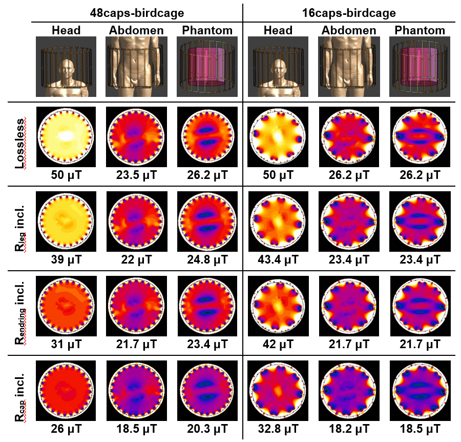
Fig.1:The simulated B1+ field of 48caps-birdcage and 16caps-birdcage when different loss cases were applied while changing the loading

Table 1: The measured Q values and the calculated resistances of the five loop coils
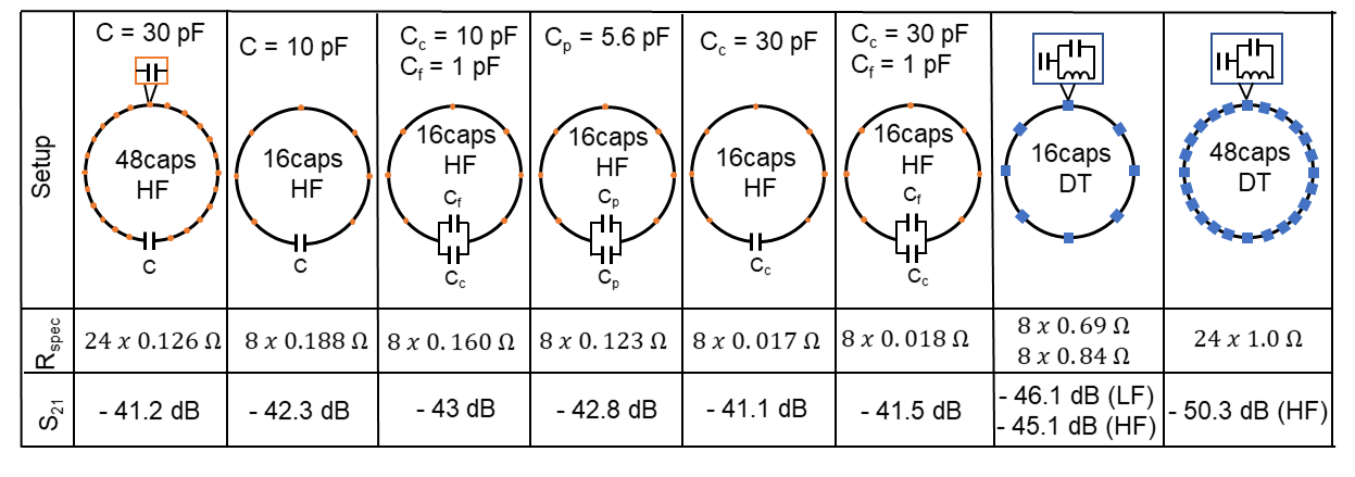
Fig.2: The measured B1+ efficiency of 48caps-birdcage and 16-caps-birdcage. HF, LF, and DT refer to high frequency, low frequency, and double tuning, respectively.
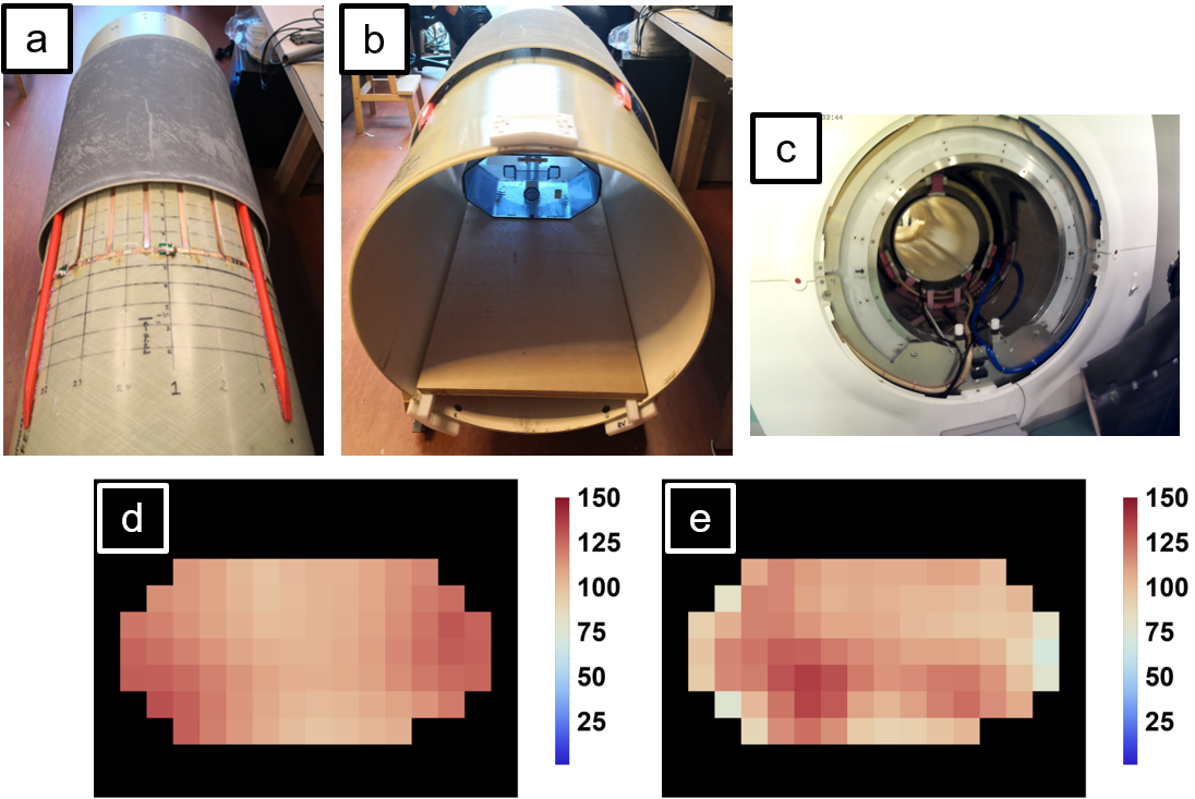
Fig.3: 16caps-birdcage (a) with the phantom inside (b). Double tuned 2H/31P borecoil embedded in the 7T scanner (c). B1 map of 2H (d) and 31P (e) of the double tuned 2H/31P borecoil. B1 maps were acquired using AFI method (4).
DOI: https://doi.org/10.58530/2023/4084