4082
Evaluation of 8-Channel Transmit Dipoles and 8-Channel Transmit Loops for Pediatric Visual Cortex Imaging at 7T
Pedram Yazdanbakhsh1,2, Christian Sprang1,3, Marcus Couch4, Richard Hoge1,2,3, Christine Lucas Tardif1,2,3, and David A. Rudko1,2,3
1McConnell Brain Imaging Centre, Montreal Neurological Institute, McGill University, Montreal, QC, Canada, 2Department of Neurology and Neurosurgery, McGill University, Montreal, QC, Canada, 3Department of Biomedical Engineering, McGill University, Montreal, QC, Canada, 4Siemens Healthcare Limited, Montreal, QC, Canada
1McConnell Brain Imaging Centre, Montreal Neurological Institute, McGill University, Montreal, QC, Canada, 2Department of Neurology and Neurosurgery, McGill University, Montreal, QC, Canada, 3Department of Biomedical Engineering, McGill University, Montreal, QC, Canada, 4Siemens Healthcare Limited, Montreal, QC, Canada
Synopsis
Keywords: High-Field MRI, RF Arrays & Systems
An 8-channel transmit radiofrequency (RF) coil array consisting of eight dipoles and another 8-channel transmit coil array consisting of 8-loops were designed, constructed and compared with each other for pediatric (4-9 years old) visual cortex imaging at 7T. To ensure robust safety of the 7T parallel-transmission (pTx) coil, local SAR matrices and the commensurate virtual observation points (VOPs) has been calculated for online SAR supervision. An 8-channel receive only array consisting of eight overlapped loops covering the back of the pediatric head area has been constructed and used inside the transmit coils for visual cortex imaging.Introduction
Pediatric imaging at ultrahigh field (UHF) is challenging because of the reduced size of the transmit coil, SAR considerations, B1+ inhomogeneity and radiofrequency (RF) penetration depth. To evaluate an optimized local transmit array to overcome some of these challenges, two different 7 T pediatric transmit coils were constructed and quantitatively compared. The comparison included simulation using CST Microwave Studio [1] and phantom imaging experiments using a Siemens 7T Terra scanner in parallel-transmission (pTx) mode. Our results demonstrate an optimized 8-channel transmit coil array, with high B1+efficiency and minimum SAR (in CP+1 mode) for imaging the visual cortex of children at 7T, can be created using eight dedicated, overlapped receive loops.Materials and Methods
Transmit Arrays:The housing of both transmit coils (Fig. 1a) was designed for complete coverage of the pediatric (4-9 years old) head with an outer diameter of 35cm, inner diameter of 24cm, and length of 26cm including two eye holes for visual stimulation (fMRI).
The first pediatric transmit coil array (Fig.1b) consisted of eight transmit dipoles (1.3cm wide). The length of each dipole is 21cm. Two variable wire-wound inductors are used in each half-wavelength dipole and a match capacitor of 5pF is used for impedance matching to 50 ohm at 297.2 MHz. Cable traps have also been used in each lambda/10 (10cm) distance for each transmit channel inside the coil. High power PIN diodes and RF chokes were used for active detuning purposes.
The second pediatric transmit coil array (Fig.1c) consisted of eight transmit loops (8cm wide by 21cm high). The two loops around the eyes were made from copper wire (wire diameter 1.25 mm2) and other loops were constructed using printed circuit board on FR4. Four symmetrically distributed fixed tuning capacitors (4 pF each), two high power variable capacitors for tune and match (to 50 ohm) and two 8pF capacitors around the match capacitor were used for each loop. Like the dipole coil design, high power PIN diodes and RF chokes were used for active detuning.
Simulation of both transmit arrays were performed in CST Microwave Studio using a 7 year old boy. The objective of the simulation step was to compare B1+ transmit efficiency distribution, SAR per accepted power (SAR/P), as well as the whole-brain average of these features in the pediatric occipital lobe.
Receive Array:
The visual cortex receive array in fig.2, consisted of an 8-element phased array with varying loop shapes and sizes (5-9 cm diameter). The loops were arranged to provide full coverage of the pediatric (4-9 years old) occipital lobe. Each Rx loop was built with 3 different safety factors: 1) active detuning 2) passive detuning and 3) RF fuses to maximize safety aspects for 7T pediatric imaging. Each loop in Fig.2 was tuned to 297.2 MHz and eight “Wan Tcom“ preamplifiers [2] were used.
Experimental imaging results were collected using the two transmit arrays (with the visual cortex receive array) using a 7T whole body MR system (Siemens Terra 7T, pTx mode).
Results and Discussions
Fig. 3 shows EM simulation results for the B1+ efficiency distribution and SAR distribution (CP+1 mode). The maximum B1+ efficiency for the dipole array was 5.2 uT/sqrt(W) in 5cm from back of the head, with an average of 4.7 uT/sqrt(W). The maximum B1+ efficiency for Loop array was 4.3 uT/sqrt(W) in 3.9cm from back of the head, with an average of 4.1 uT/sqrt(W).The peak 10-g-average SAR over the accepted power for dipole array was 0.87 kg-1 (transmitting in CP+1mode) and 0.64 kg-1 for the loop array.
Both transmit loop and dipole array had a reflection coefficient (S11) of -15dB to -20dB for all channels. The transmission coefficient (S21) of -8dB to -25dB were measured for loop array and -11dB to -28dB for the dipole array loaded with a human head. The ratio of unloaded‐to‐loaded quality factors (Qu/QL) was 1.5 for each loop and 1.3 for each dipole when loaded with the phantom.
The 8 receive loops had S11 values between -15dB and -25dB and S21 values between -12dB and -25dB when loaded with a human head. The Q-ratio (Qu/QL) of the Rx elements varied from 1.2 to 1.5.
Fig. 4 shows the noise correlation matrix for the eight receive loops and the experimental and simulation B1+efficiency results for loop and dipole array (CP+1). Fig 5 shows representative SNR from axial gradient-echo images with same background noise for the pTx Nova head coil (8CH transmit and 32CH receive in pTx mode), dipole array and loop array. A comparison between distributed SNR can be seen in this figure.
Conclusion
The simulated maximum B1+ efficiency for the dipole array was around 10% better than the loop array. The peak 10-g-average SAR over the accepted power for dipole array was around 35% worse than the loop array (CP+1 mode). B1+ distribution simulation and SNR experimental results indicated that the loop array has more signal close to the back of the head than the dipole but after around 10mm from the back of the head to the center of brain, dipole array has around 200% more signal than the loop array. In a distance around 60mm they will have roughly the same signal.Acknowledgements
No acknowledgement found.References
[1] CST studio suite 2017 (CST, Darmstadt, Germany)
[2] https://www.wantcominc.com
Figures
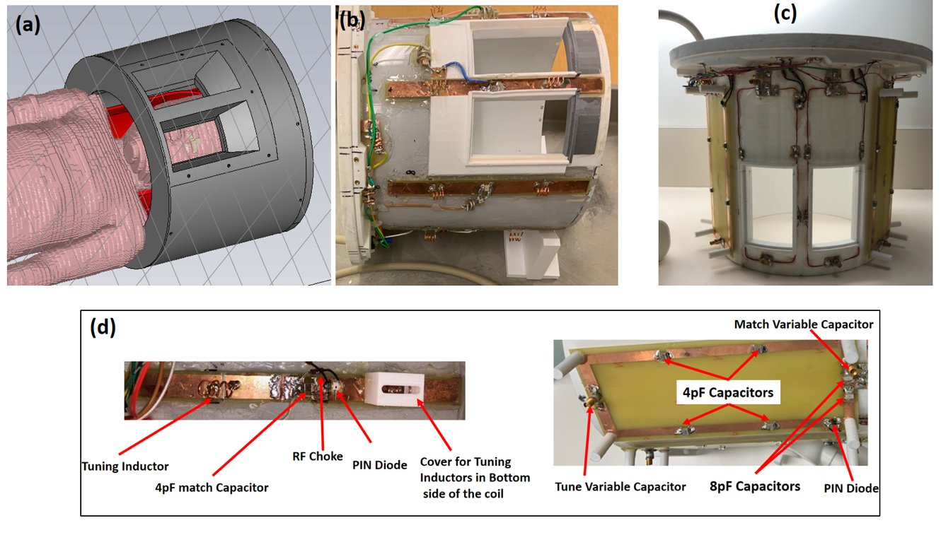
Figure 1: a) The housing of both transmit coils with
Outer diameter of 35cm, Inner diameter of 24cm and length of 26cm with enough
space for the receive array and wholes for fMRI studies, (b) Constructed 8CH
Transmit Dipole array, (c) Constructed 8CH Transmit Loop array, (d): Left: one
Transmit dipole in (b), right: one transmit loop in (c)
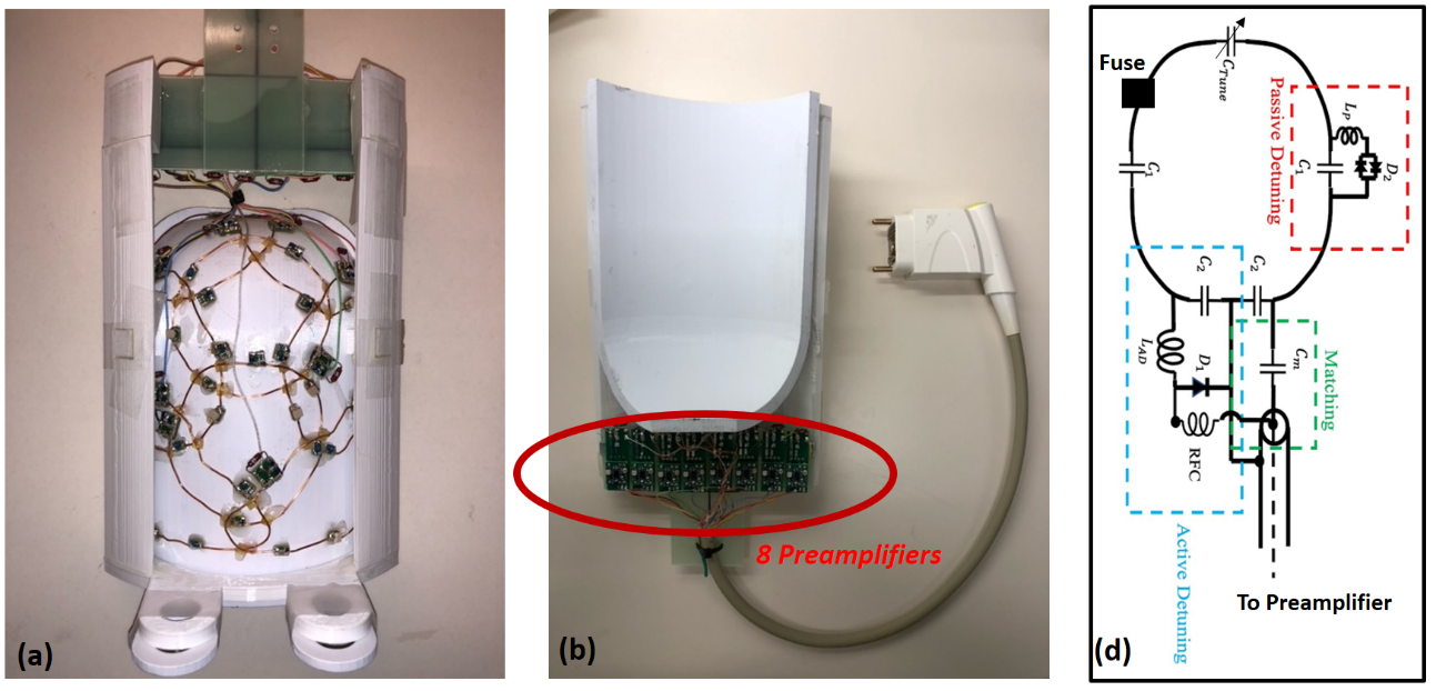
Figure 2: a) Bottom view of the
eight-channel receive array for pediatric visual cortex imaging b) top view and
8 preamplifiers C) Circuit schematic of single receive coil C_m
(C_match)=10-15pF, C_tune=Variable capacitor (1pF-10pF),
c1=5pF, c2=10 pF
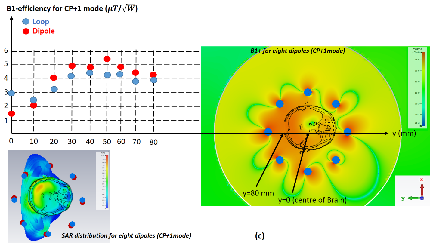
Figure
3: CST EM Simulation of a)
8 Channel Transmit Loop b) 8Channel Transmit Dipoles using 7 years old Boy
model (c): right: B1+ field for eight dipoles (CP+1 mode)
from the central transversal slice, left top: B1+ distribution
for both dipole array and loop array from the back of the head to the centre of
brain, bottom left: SAR distribution for CP+1 mode for eight dipoles
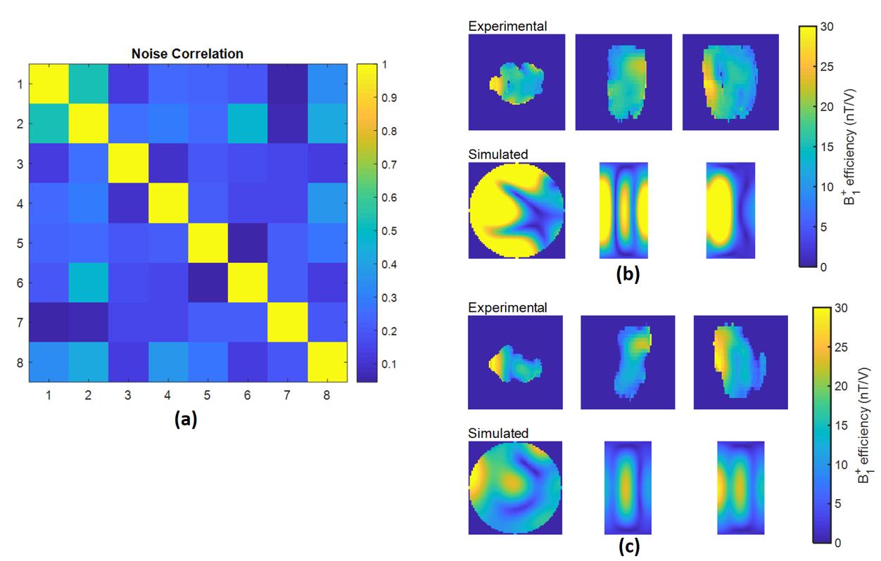
Fig
4: (a) The noise correlation matrix for eight receive loops with a mean of 48%
and a max of 58%. (b) Experimental and simulation results for the loop array
(CP+1), (c): Experimental and simulation results for the dipole
array (CP+1) using Siemens standard plastic bottle phantom (per
1000g H2O dist.:1,25g NISO4 x 6 H2O+5g NaCl)
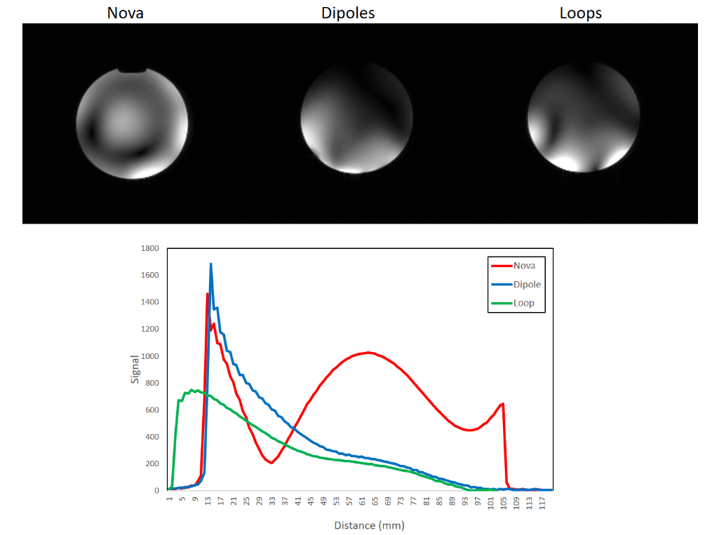
Fig
5: axial gradient-echo images with same background noise for the pTx Nova Head
coil with 8CH Transmit and 32CH receive (left), Dipole Array as transmit coil
and 8CH receive array (middle), Loop Array as transmit coil and 8CH receive visual
cortex array as receive coil(right). The comparison between the SNR with same
background noise for all 3 coils (bottom). All in CP+1 mode using
Siemens standard plastic bottle phantom (per 1000g H2O dist.:1,25g
NISO4 x 6 H2O+5g NaCl)
DOI: https://doi.org/10.58530/2023/4082