4075
Investigating the Optimal Number of Channels in an Array System for Human Head Imaging at 7T1Department of Biomedical Engineering, State University of New York at Buffalo, Buffalo, NY, United States
Synopsis
Keywords: High-Field MRI, RF Arrays & Systems
To determine the optimal number of channels employed in an array system for Human Head imaging at 7T, we examined different multi-channel circular LC loop array systems, ranging from 4-channel to 64-channel arrays.
Introduction
When the number of channels in an array increases, parallel imaging performance improves [1,2], improving image acquisition time and reducing susceptibility artifacts. Although more channel numbers improve parallel imaging, they also introduce design challenges in array systems, such as increased inter-element coupling due to closely placed elements [3]. Further, it also causes a significant reduction in field penetration due to the use of small-diameter coils for a given space, which adversely affects the SNR. Some analysis must be performed to identify the ideal number of channels to use in an array. We numerically modeled circular LC loop array systems with channel numbers ranging from 4 to 64 to understand better if an optimal combination of channel numbers would increase parallel imaging performance while simplifying design complexity.Method
We modeled seven multi-channel array configurations: 4,8,12,18,24,32, and 64-channel arrays. The channel sizes in each array configuration were chosen to ensure that the region covered by each array system is identical. As a result, smaller channel number arrays had larger channels than larger channel number arrays. Thus, the 4-channel array had four LC loops with a diameter of 19.2 cm, while the 8-channel array had eight LC loops with a diameter of 16.8 cm. Furthermore, the LC loop diameters for the 12, 18, 24, 32, and 64-channel array designs were 13.8 cm, 11.4 cm, 10.6 cm, 8.6 cm, and 6 cm, respectively. Every channel in every configuration had the same diameter of 8mm. Fig1. depicts all of the array configurations. To ensure a comparable playing field for all array systems, we fed all channels through separate lumped ports with a 1 Ampere source and appropriate phase based on channel location. The 1 Ampere current source ensured that all channels were tuned and decoupled at 300MHz, providing optimum conditions for fairly comparing the performance of each array. We evaluated the array configurations around a human-head-shaped phantom, as shown in Fig1. We examined two conditions: i) Unloaded/Free Space, where the Human-head-shaped phantom we employed was assigned air properties with relative permittivity εr:1, electrical conductivity σ :0 S/m, and ii) Loaded case, in which the phantom was assigned the dielectric properties of the human brain, with relative permittivity εr:60 and electrical conductivity σ :0.692 S/m. Finally, we measured the peak and average B1 at the phantom's center. To assess the B1 at the center, we defined an 8cm diameter circular-shaped region of interest in the phantom center's transverse, sagittal, and frontal planes. Peak and average B1 values were calculated for the indicated regions.Results
Fig2 depicts the Unloaded/Free space B1 plots in the air-filled phantom's transverse, sagittal, and frontal regions of interest. The top three peak B1(µT) values in the transverse region of interest (19.2 µT,18.8 µT,15 µT) were generated by 8,12, and 24-channel arrays, respectively, while the top three average B1(µT) values (16 µT,14.3 µT,14 µT) were generated by 12,24, and 8-channel arrays, respectively. Furthermore, in the sagittal region of interest, the top three peak B1(µT) values were generated by 8,24, and 12-channel arrays, respectively, while the top three average B1(µT) values were generated by 12,24 and 8-channel arrays, respectively. Finally, in the frontal region of interest, the 12,8, and 24-channel arrays produced the top three peak B1(µT) values (18 µT, 16.5 µT, 16.5 µT), respectively, whereas the 12,24,8-channel arrays produced the top three average B1(µT) values (15.7 µT,14.1 µT,12.6 µT). The loaded B1 plots in the transverse, sagittal, and frontal regions of interest of the phantom assigned the dielectric properties of the human brain are shown in Fig3. The evaluated values were higher than those of the unloaded/free space case. In the transverse region of interest, 8,12,24-channel arrays produced the top three peak B1(µT) values (40.2 µT,35.9 µT,17.8 µT) and the top three average B1 values (29 µT,24.6 µT,13.02 µT), respectively. In the sagittal region of interest, the highest three peak B1 values (41.9 µT, 36 µT, and 19.1 µT) were obtained by 8,12,24-channel arrays, respectively. In contrast, the top three average B1 values in the sagittal region of interest were generated by 12,8, and 24-channel arrays, respectively. Finally, in the frontal region, 12,8,24-channel arrays produced the top three peak B1 values (36µT,35.7µT,19.1µT) as well as the top three average B1 values (27.62 µT,26.4 µT,13.21 µT), respectively. Fig4 displays tabulated peak and average B1 data for all array configurations and evaluated cases, as well as graphs for each region of interest displaying the pattern of peak and average B1 sensitivity based on the number of channels in the array system.Discussion/Conclusion
We investigated various multi-channel LC loop arrays for human head imaging at 7T to determine the optimal number of channels in an array system. Based on our results, we found out that the 12-channel array produced the highest average B1 values in regions of interest than the rest in the free space scenario and also dominated in the same pattern by producing the highest average values in 2 of the three regions of interest evaluated in the loaded case. We also found an approximately 2-fold increase in the B1 values in the loaded case than the free-space scenario.Acknowledgements
This work is supported in part by the NIH under a BRP grant U01 EB023829 and by the State University of New York (SUNY) under the SUNY Empire Innovation Professorship Award.
References
1. K. Pruessmann, et al., "SENSE: Sensitivity encoding for fast MRI", Magn Reson Med, 42:952-962 (1999)
2. J. Ji, et al., "Parallel and sparse MR imaging: methods and instruments-Part 2", Quant Imaging Med Surg, 4:68-70 (2014)
3. Y. Li, et al., "ICE Decoupling Technique for RF Coil Array Designs", Medical Physics, 38(7): 4086- 4093 (2011)
Figures
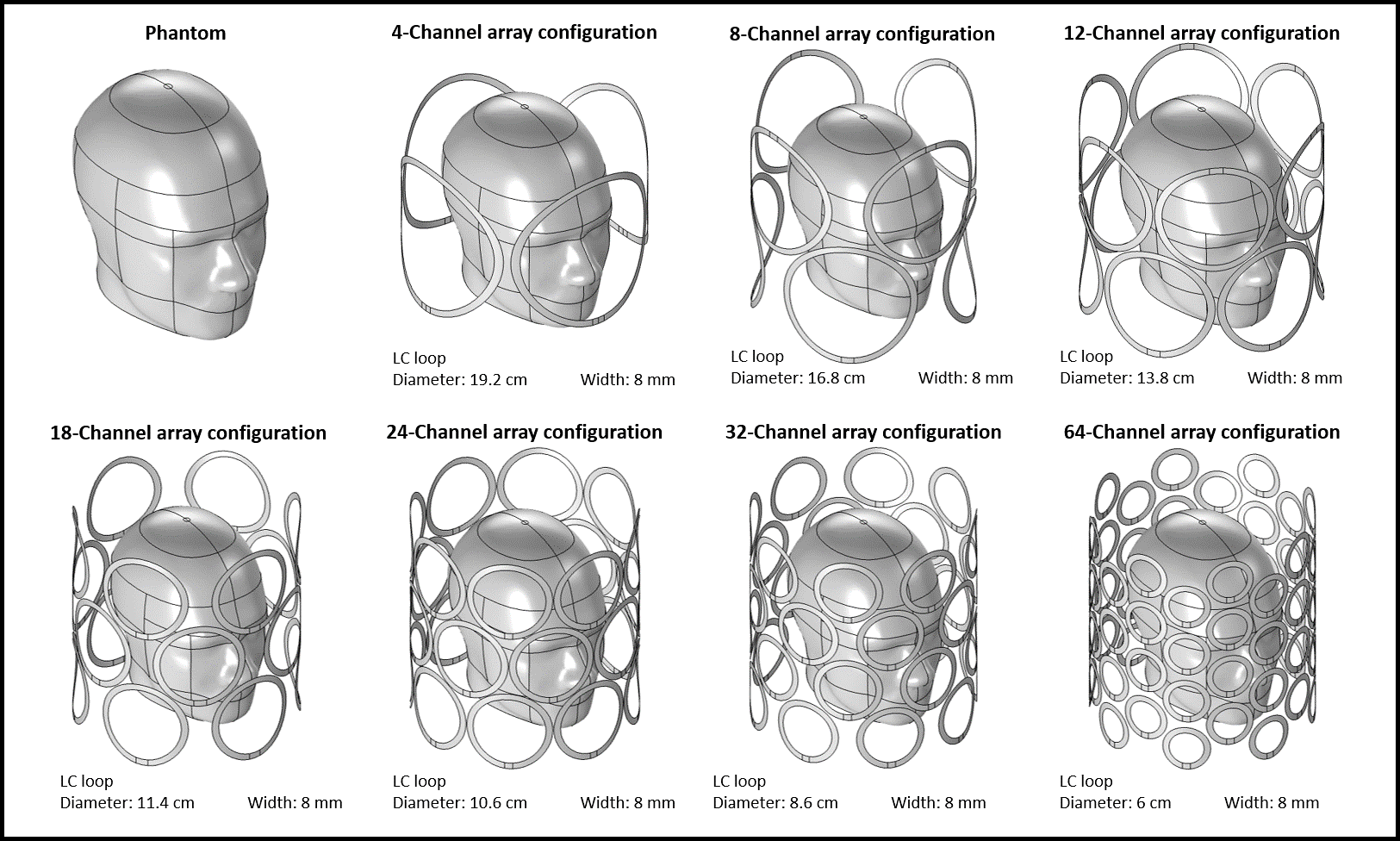
Figure 1. The figure shows the Human-head-shaped phantom used in the array simulations. The top row shows 4,8, and16-channel configurations, and the bottom row shows the 18,24,32, and 64-channel configurations.
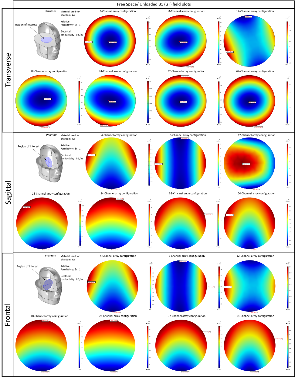
Figure 2. Free space/Unloaded B1(µT) plots in transverse, sagittal, and frontal interest zones. The figure also depicts the locations of the regions of interest used to calculate the peak and average B1 values. Because of the wide range of values, the color scales for each configuration differ and are based on the maximum and minimum values produced in each configuration.
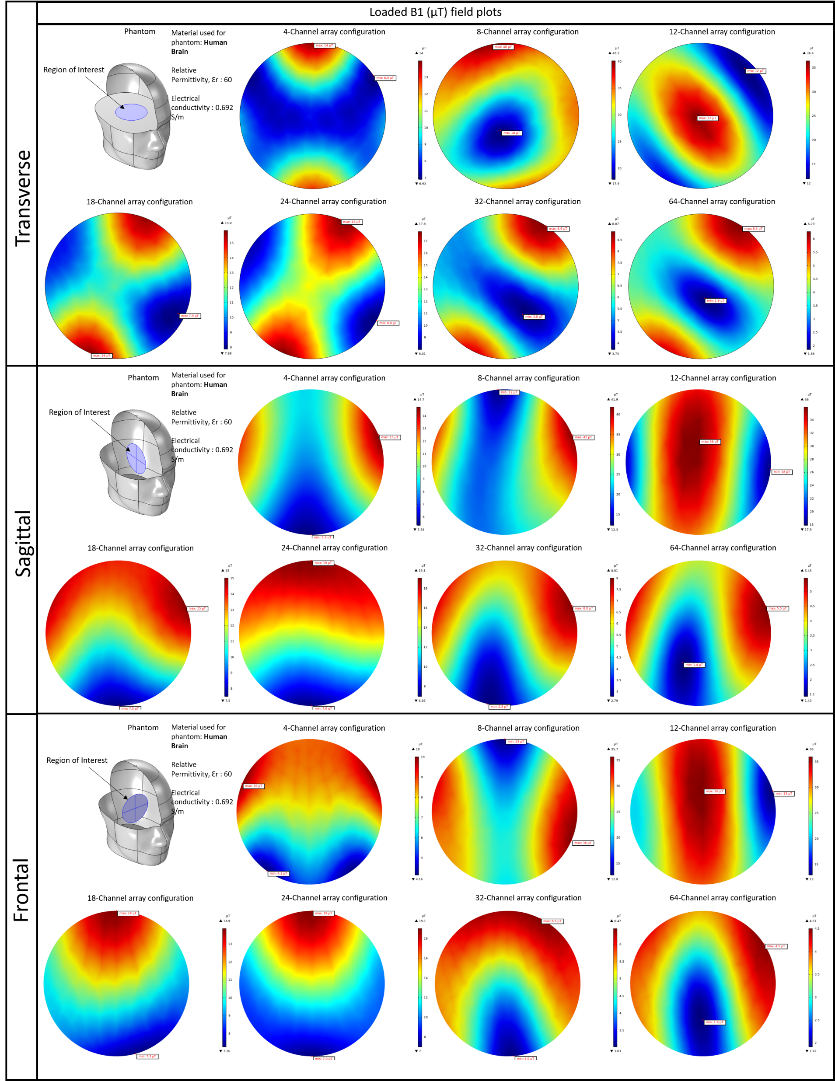
Figure 3. Loaded B1(µT) plots in transverse, sagittal, and frontal interest zones. The figure also depicts the locations of the regions of interest used to calculate the peak and average B1 values. Because of the wide range of values, the color scales for each configuration differ and are based on the maximum and minimum values produced in each configuration.
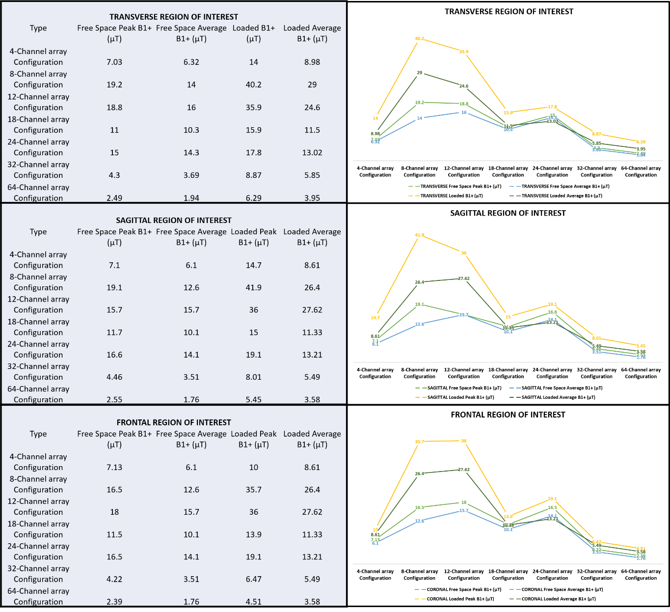
Figure 4. Peak and average B1 (µT) values for each region of interest generated by the array configurations are tabulated. The left column has tabulated data, while the right column contains graphs that correspond to the adjacent tabular data and show the pattern of variations in peak and average B1 values dependent on channel numbers.