4071
En Route to Body and Cardiac MRI at 21.0 T: Where does the RF power dissipate?1Max-Delbrück Center for Molecular Medicine in the Helmholtz Association, Berlin, Germany, 2Experimental and Clinical Research Center (ECRC), a joint cooperation between the Charité Medical Faculty and the Max-Delbrück Center for Molecular Medicine, Berlin, Germany, 3MRI.TOOLS, Berlin, Germany
Synopsis
Keywords: RF Arrays & Systems, Bioeffects & Magnetic Fields
Investigation of the power correlation matrix at 21.0 T is vital to elucidate the electrodynamics for human body and cardiac MR as well as the RF antenna performance. Recognizing this opportunity, this abstract assesses the power losses for multi-channel RF transceiver arrays for human body and cardiac MR using 32-channel pTx/Rx self-grounded bow-tie building block (SGBT). Losses were determined inside the tissue, lossy material of the antenna, lumped elements of the tuning and matching network and due to coupling and radiation.Introduction
Pushing the boundaries of UHF-MR and unlocking the potential of extreme field MR (EF, B0≥14.0T) [1] motivates research into the electrodynamics. Loss analysis will be a major key to understand the electrodynamic constraints and is essential for developing RF coils tailored for body and cardiac EF-MR. Assessing where the power at EF dissipates will help us to minimize the undesired losses outside the tissue as well as the comparison of different array designs. Recognizing this opportunity this work elucidates the loss mechanism at high spin excitation frequency (f=900MHz) using a 32-channel RF array based upon self-grounded bow-tie building blocks (SGBT) [2].Methods
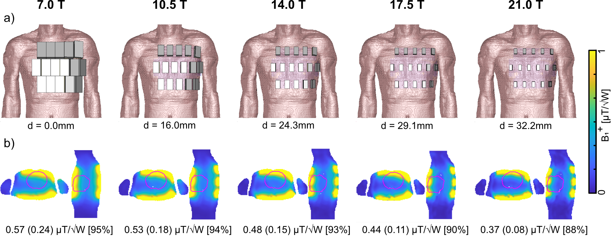
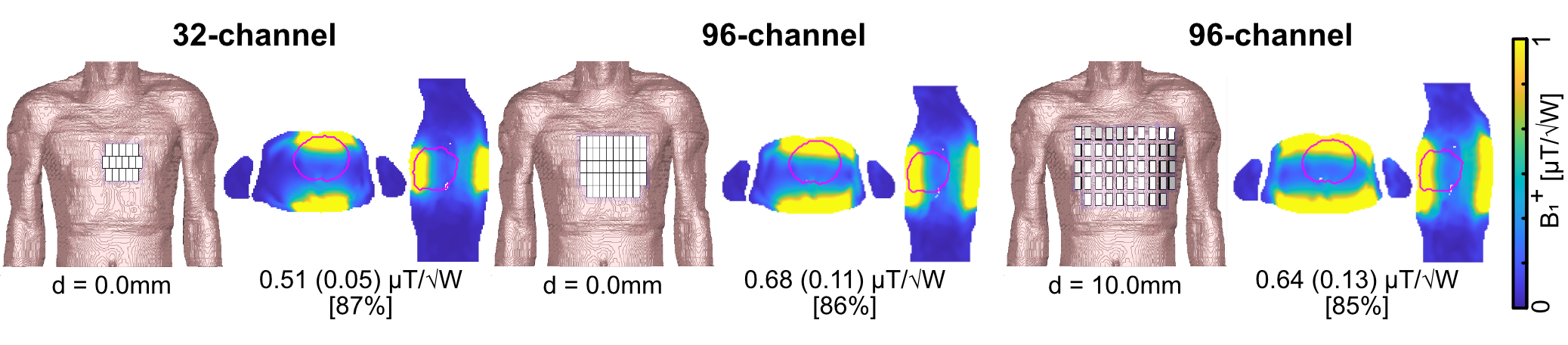
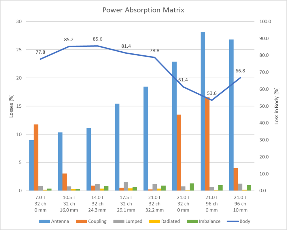
To investigate the loss mechanism as a function of the magnetic field strength (B0) five 32-channel SGBT arrays were modeled on the human voxel model Duke [3] (Figure 1a). With increasing B0 the antenna dimensions were adapted to the 1H resonance frequency at 7.0T (f=297.2 MHz) to 21.0T (f=900 MHz). The shortened antennas were modeled at the identical center positions at each B0 resulting in an increased nearest neighbor distance (d). Furthermore, at 21.0T three high-density RF arrays with 32 (d=0mm) and 96 elements (d=0mm;10mm) were modeled (Figure 2). For each SGBT a lossy parallel capacitor and a lossy serial inductor were used for tuning and matching. EMF simulations were performed in CST Microwave Studio 2020. The electrical material parameters of the antennas and the tissue parameters provided by the IT‘IS Foundation [4] were adapted to the corresponding resonance frequency. Using a framework for the calculation of the power correlation matrices [5] the loss terms for the RF arrays were evaluated in Matlab 2019b. Using the power correlation matrix and the single channel B1+ amplitude the intrinsic (only sample losses) and realistic (sample, coil, and coupling losses) transmit efficiency (TXE) were evaluated in the entire 3D heart [6]. The sum of the magnitude of the superposed B1+ yields theoretical upper bounds for the RF arrays regarding TXE.Results
A worst-case reflection of Sii < −15.6 dB was observed for all setups. At 21.0T the RF array revealed a coupling of Sij < −24.3 dB (d=32.2mm) due to the increased nearest neighbor distance and Sij < −11.6 dB (d= 0.0mm) for the high-density RF arrays (Table 1). At 7.0T 77.8% of the power dissipates into Duke, 11.8% in coupling, and 9.0% in the antenna (Figure 3). At 21.0 T with d= 32.2mm, 78.8% of the power dissipates into Duke, 0.2% in coupling, and 18.5% in the antenna. For the 96-channel high-density array (d=10mm) revealed 66.8% of the power dissipates into Duke, 4.0% in coupling, and 26.8% in the antenna. Losses in lumped elements and radiation accounted less than 1.6% for all setups for each field strength. The inaccuracy of the power correlation matrix was below 1.3%. The superposed B1+ maps (Figure 1b) revealed for the 7.0T setup a mean (min) TXE (realistic) of 0.57 (0.24) μT/√W and for the high-density array (d=10mm) at 21.0T 0.64 (0.13) μT/√W (Figure 2).Discussion
Highest undesired losses were found in the antenna and coupling. The higher field strengths revealed increased losses in the antenna. The distance between the antennas plays a vital role in the loss mechanism where a closer setup causes more interaction between the antennas resulting in additional losses and vice versa. The shortened antennas enabled an improved channel count of 96 elements where the enhanced distance (0mm -> 10mm) revealed lower losses in the antenna and coupling resulting in a higher power transfer into the body. The narrow field of view (FOV) of the shortened antennas and the enlarged distance (d=32.2mm) between the antennas towards 21.0T caused less interference of the individual EMFs. This and the higher losses at 21.0T resulted in a lower TXE compared to the 7.0T baseline setup with an identical channel count (Figure 1b). The closer setup of the 32-channel array showed a better overlap of the EMFs which resulted in a higher mean TXE compared with distanced antennas. Yet, with 32-channel the minimum TXE could not be addressed which is one of the main challenges of cardiac MR. The 96-channel setup with a higher degree of freedom for B1+ shaping showed higher minimum TXE compared to the 32-channel setup. The high-density RF array with enhanced channel count and distance is beneficial to achieve the highest TXE.Conclusion
This simulation study provides a technical foundation for the design and implementation of RF arrays tailored for body and cardiac MRI at 21.0T. The spatial arrangement of an RF array needs to ensure low coupling as well as an overlap of the individual EMFs to facilitate successful control and shaping of the transmission field. For the feasibility of body and cardiac MRI at 21.0T low loss RF antenna concepts with low mutual coupling are required in order to achieve the highest transmit efficiency.Acknowledgements
This project has received funding from the European Research Council (ERC) under the European Union's Horizon 2020 research and innovation program under grant agreement No 743077 (ThermalMR).References
1. Niendorf T, Barth M, Kober F, Trattnig S (2016) From ultrahigh to extreme field magnetic resonance: where physics, biology and medicine meet. Magnetic Resonance Materials in Physics, Biology and Medicine 29 (3):309-311.
2. Eigentler TW, Kuehne A, Boehmert L, Dietrich S, Els A, Waiczies H, Niendorf T (2021) 32-Channel self-grounded bow-tie transceiver array for cardiac MR at 7.0T. Magn Reson Med 86 (5):2862-2879.
3. Christ A, Kainz W, Hahn EG, Honegger K, Zefferer M, Neufeld E, Rascher W, Janka R, Bautz W, Chen J, Kiefer B, Schmitt P, Hollenbach HP, Shen J, Oberle M, Szczerba D, Kam A, Guag JW, Kuster N (2010) The Virtual Family - Development of surface-based anatomical models of two adults and two children for dosimetric simulations. Physics in Medicine and Biology 55.
4. Foundation II (2018) Tissue Properties Database V4.0. doi:10.13099/VIP21000-04-0.
5. Kuehne A, Goluch S, Waxmann P, Seifert F, Ittermann B, Moser E, Laistler E (2015) Power balance and loss mechanism analysis in RF transmit coil arrays. Magn Reson Med 74:1165-1176.
6. Georgakis IP, Polimeridis AG, Lattanzi R (2020) A formalism to investigate the optimal transmit efficiency in radiofrequency shimming. NMR Biomed 33:1-18.
Figures