3911
Considerations for Accurate Active Detuning Measurements in Densely Parallel Array Coils1Institute of Medical Physics and Radiation Protection, TH Mittelhessen University of Applied Sciences, Giessen, Germany, 2A.A. Martinos Center for Biomedical Imaging, Massachusetts General Hospital, Harvard Medical School, Boston, MA, United States
Synopsis
Keywords: RF Arrays & Systems, High-Field MRI, detuning
Active detuning of receive array coil during transmit prevents large currents being induced in the coil which could damage sensitive electronic components and create SAR hotspots. The standard method of adjusting active detuning using a double probe shows an offset in the resonant frequency set at bench when tested in the presence of a scanner. Setting a high impedance at the input of loop using S11 measurement exactly at Larmor frequency has proven to be a better method to detune loops actively.
Introduction
During RF excitation, the receive coil must be detuned to avoid large currents being induced in the coil, which could damage sensitive electronic components and create SAR hotspots with severe patient hazards1. The most common approach to detuning receive coil is incorporating an actively controlled detuning trap into each loop of the receive coil. The detuning trap comprises a PIN diode in series with a variable inductor, which together with the capacitor from the loop resonates at the Larmor frequency. Thus, when the PIN diode is forward biased (transmit mode), the resonant parallel LC circuit inserts a high impedance in series with the coil loop, blocking current flow at the Larmor frequency during transmit.The commonly used method for adjusting the detuning trap is a S21 measurement between two inductive probes (double probe) lightly coupled to the coil element, with the "active detuning dip" set precisely at the Larmor frequency. However, this standard method appears to show an offset in the measurement carried out at the bench when detuning array coils consisting of small loop elements. We assessed this problem with bench measurements using different loop sizes and further analyzed these conditions with simulations.
Methods
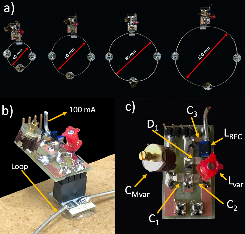
Bench Measurement: Four different loop sizes; 40 mm, 60 mm, 80 mm, and 100 mm, were considered for the bench measurement (Figure 1a). The loops were tuned and matched to the Larmor frequency 123.25 MHz at 3T. An active detuning trap was formed around C2 using a variable inductor Lvar and a PIN diode D1 (Figure 1c). When the diode was forward biased with 100 mA, it formed a parallel resonant LvarC2 circuit, generating a high impedance in series with the coil loop, blocking current flow at Larmor frequency. We adjusted and monitored the active detuning traps of all four loops using three different methods: i.) the standard double probe S21 measurement (Figure 2a), ii.) a direct S11 measurement, that required the loop element to be opened (Figure 2b), and iii.) a single-loop S11 pick up probe (“sniffer” probe) of the isolated detuning trap (not attached to the loop) (Figure 2c).Simulation: To assess the current flow in the loop during transmit, a simulation (HFSS, ANSYS, USA) was performed using a lowpass birdcage as a transmit coil and a rectangular loop as a receive coil (Figure 3a). A cylindrical phantom corresponding to a human brain (εr = 63, σ = 0.46 S/m) was placed at the center. The birdcage and the loop were tuned and matched under the presence of the phantom individually and then two co-simulations for S21 measurement between Port 1 (birdcage) and Port 2 (loop) were carried out: i.) with an optimal Lvar(61.8 nH) value (Figure 3b), where the resonant frequency of the detuning trap is same as the Larmor frequency and ii.) with a poorly adjusted Lvar (65 nH).
Results
Adjusting the “active detuning dip” while monitoring this measurement with the double probe resulted in an offset to the desired Larmor frequency of 5.3, 5.8, 6.6 and 17.6 MHz for the 100mm, 80mm, 60mm and 40mm loop sizes, respectively (Figure 4). Both, the sniffer probe measurements and the direct S11 measurements did not show any frequency offset. Emulating just a small offset of 3.3 MHz in the simulation showed a corresponding 10-fold increase in current flow on the loop’s copper surface (Figure 5c-d).Discussion
The adjustment of active detuning traps of array coils consisting of small loop elements is prone to suboptimal adjustment when using the S21 double probe method. This effect diminishes as the size of the loop elements increases. Setting a high impedance at the input of the loop via S11 direct measurement provided a perfect detuning trap with a resonant frequency exactly at the Larmor frequency which was validated by the sniffer S11 measurement. Furthermore, simulation results show that slight changes in the resonant frequency of the detuning trap differing from the Larmor frequency give rise to a large current flow on receive coils during transmit.Conclusion
The double probe measurement method for setting active detuning shows an offset in the resonant frequency of the detuning trap and Larmor frequency. The smaller the loop, the less accurate the measurement. A direct S11 measurement for adjusting active detuning by measurement of the actual detuning impedance is more reliable when building multi-channel coils consisting of small loop elements.Acknowledgements
References
1. Keil B, Wald LL. Massively parallel MRI detector arrays. J Magn Reson. 2013 Apr;229:75-89.
2. Keil B, Blau JN, Biber S, Hoecht P, Tountcheva V, Setsompop K, Triantafyllou C, Wald LL. A 64-channel 3T array coil for accelerated brain MRI. Magn Reson Med. 2013 Jul;70(1):248-58.
3. Schmitt M, Potthast A, Sosnovik DE,
Polimeni JR, Wiggins GC, Triantafyllou C, Wald LL. A 128-channel receive-only
cardiac coil for highly accelerated cardiac MRI at 3 Tesla. Magn Reson Med.
2008 Jun;59(6):1431-9.
Figures
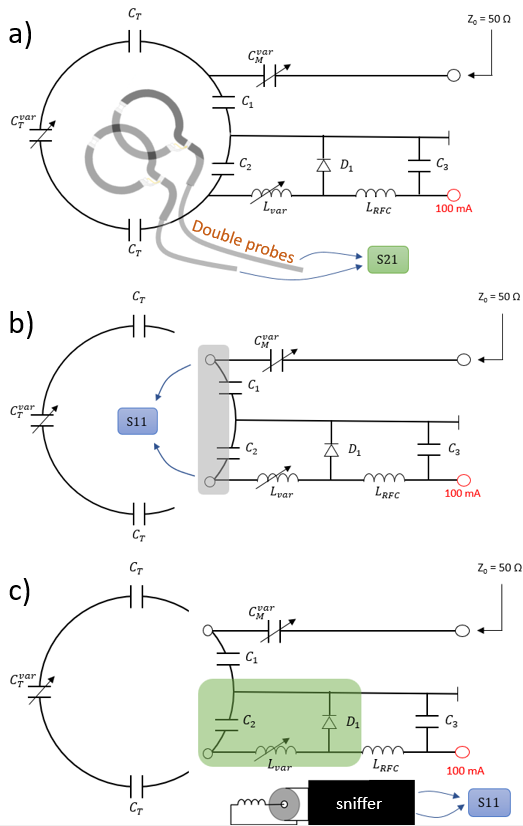
a) S21 measurement with a double probe, b) Setting loop input impedance with S11 measurement, c) S11 sniffer measurement near detuning trap to measure the resonant frequency of the trap
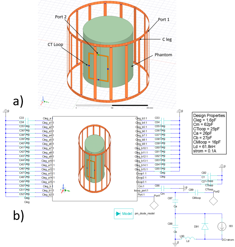
a) a lowpass Birdcage, a rectangular loop coil, and a cylindrical phantom design for HFSS Simulation, b) Circuit and design properties for co-simulation in HFSS
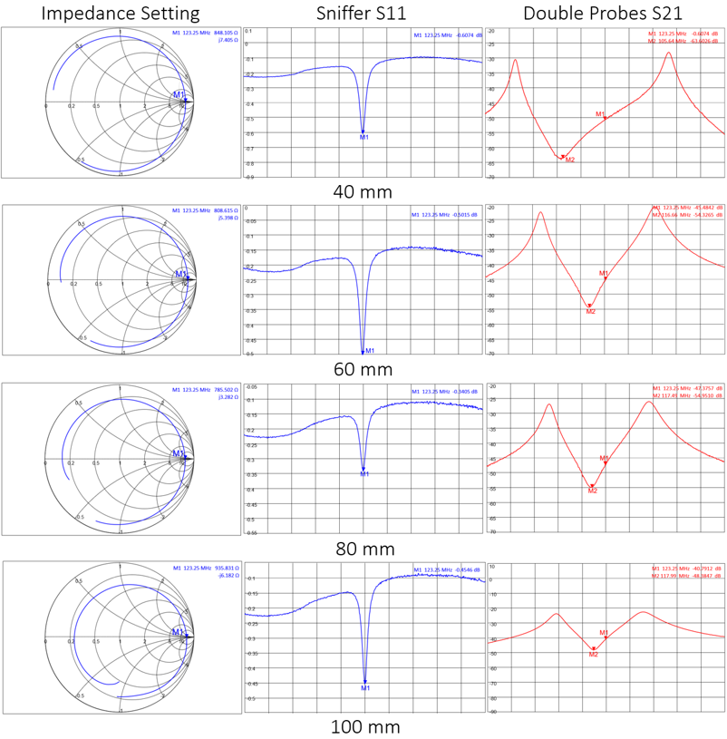
Setting a high impedance at loop input for each loop, validating it with a sniffer S11 measurement and verifying the offset seen with S21 measurement done by a double probe
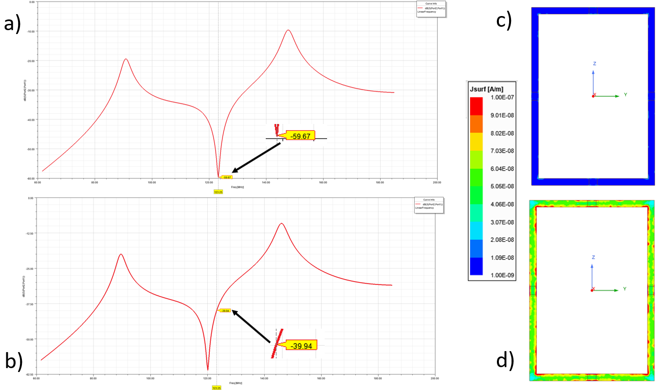
Simulation results: a) S21 report with an optimal Lvar(61.8 nH) value, b) S21 report with poorly adjusted Lvar(65 nH) value, c) current flow on the loop surface during transmit with an optimal Lvar value, d)current flow on the loop surface during transmit with poorly adjusted Lvar value