3910
A coupled planar RF array for ultrahigh field MR imaging
Yunkun Zhao1, Komlan Payne1, Leslie YIng1, and Xiaoliang Zhang1
1Biomedical Engineering, State University of New York at Buffalo, Buffalo, NY, United States
1Biomedical Engineering, State University of New York at Buffalo, Buffalo, NY, United States
Synopsis
Keywords: New Devices, Spinal Cord
This study proposes a coupled planar radio frequency (RF) array for spine imaging at 7T. Multiple identical loop coils are closely placed to achieve strong EM coupling in order to form a multimodal resonator. This coupled resonator can design large high-frequency RF coils for ultrahigh field imaging applications in humans.Introduction
Radiofrequency coils are critical components of the MRI system. While other conditions remain unchanged, the size of the RF coil is inversely proportional to the resonance frequency of the RF coil. Because of the limitations of the electrical properties of the RF coil components, it is challenging to design large-size high-frequency RF coil coils for human imaging at ultrahigh fields. In this study, we proposed and investigated the use of coupled planar RF coil array to have a large imaging area coverage and achieve a high resonant frequency with the individual resonators operating at relatively low frequencies. These large-size high-frequency coils can be used as a transceiver or transmit-only coils.Methods
The proposed RF coil array is designed on a plane, as shown in Fig.1A. We designed a 10×10 cm2 LC circuit coil to fit the human spinal cord width, and coils were arranged in sequence into a coil array on a 2-dimensional plane. The material we used for the coil is 16AWG copper wire which has a 1.291mm diameter. The array includes five identical LC coils and one driving coil for inductive driving. The driving coil only has one port and is located at the very edge of the array. Other LC coils have four tuning capacitors with 3.9pF and have an intrinsic resonant frequency of 271MHz to achieve 300MHz (the Larmor Frequency of proton 1H at 7T) after coupling with other coils. Only the area covered by five LC coils will be used for imaging. A phantom of 50×10×5 cm2 was placed 1cm above the five LC coil arrays to observe the magnetic field distribution. Another large size single coil which has size with the coil array, has also been made for result comparison as shown in Fig.1B. The single coil for comparison has a size of 50×10 cm3, uses 12 tuning capacitors with 2.15pF, and has a matching circuit with two matching inductors with 0.04nH and 0.02nH to tune the coil at 300MHz. The single large-size coil has the same imaging coverage area as the coil array and the same size phantom above the coil. Scattering parameters evaluated the performance of the coil array in the coupling, and in imaging, it was evaluated by the B1 field distribution plot. All magnetic field plot has been normalized to 1W input power. Numerical results of the proposed designs are obtained using electromagnetic simulation software CST Studio Suite (Dassault Systèmes, Paris, France).Results
Fig.2 shows simulated scattering parameters versus the frequency of the RF coil array. According to the scattering parameters, there are five resonant modes generated by this coupled 5-element array. Fig.3 shows the magnetic field distribution and direction of those five modes. As shown in the figure, among all the resonant frequencies, mode 5, with the highest resonant frequency (300MHz) among others, can generate magnetic fields with a similar pattern as a regular loop coil, which has the potential for imaging. Fig.4 shows the magnetic field strength within the imaging phantom generated by the coupled array and a traditional loop coil of the same size. The results also show that the coupled array coil can generate stronger B1 fields over the traditional loop coil. Fig.5 illustrates the coronal plot of field strength at y=20mm and x=0mm within the phantom. The numerical result shows that the average field strength of the coil array is 363.3% higher than the field strength of a transitional loop coil.Conclusion
In this study, we designed a coupled planar RF array that can be used for ultrahigh-field spine imaging applications. The coupled planar RF array shows the ability to operate at high frequency and provides a large imaging coverage with a stronger B1 field over the traditional loop coil of the same size. This technique of coupled coil array provides a potential method for designing high-frequency large-size RF coils for ultrahigh field MR imaging.Acknowledgements
This work is supported in part by the NIH under a BRP grant U01 EB023829 and by the State University of New York (SUNY) under SUNY Empire Innovation Professorship Award.References
1. Roemer PB, Edelstein WA, Hayes CE, Souza SP, Mueller OM. The NMR phased array. Magn Reson Med. 1990 Nov;16(2):192-225. doi: 10.1002/mrm.1910160203. PMID: 2266841.
2. Li Y, Xie Z, Pang Y, Vigneron D, Zhang X. ICE decoupling technique for RF coil array designs. Med Phys. 2011 Jul;38(7):4086-93. doi: 10.1118/1.3598112. PMID: 21859008; PMCID: PMC3139506.
Figures
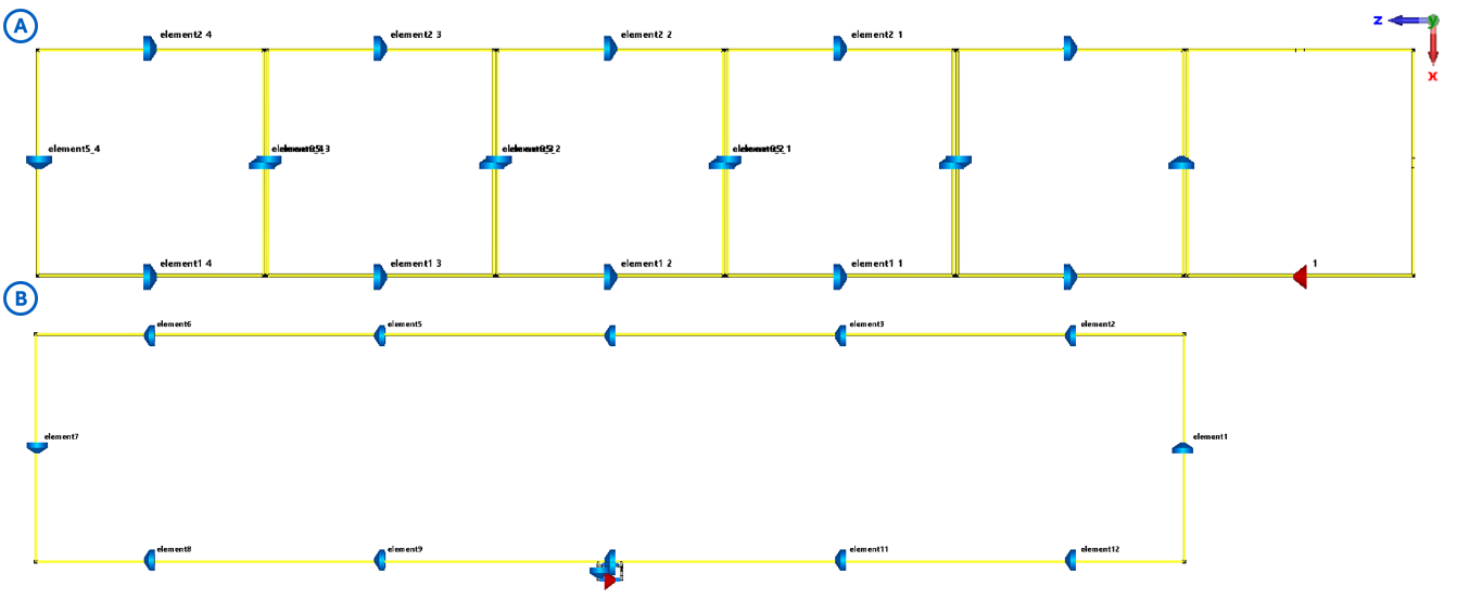
Fig. 1. (A) LC coil
array setup (B) Single large size coil setup.
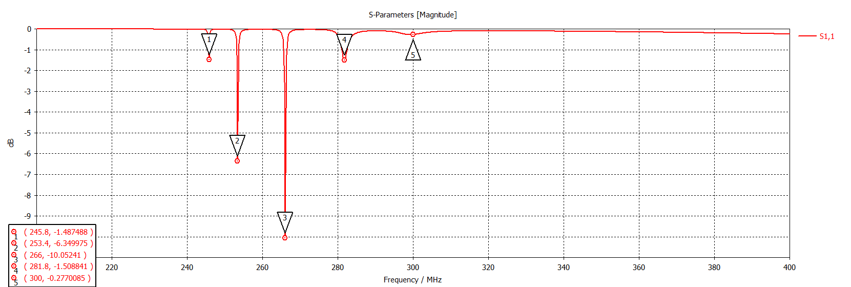
Fig. 2. Simulated scattering parameters of RF coil array show strong
coupling and higher resonant frequency compared with the original coil.
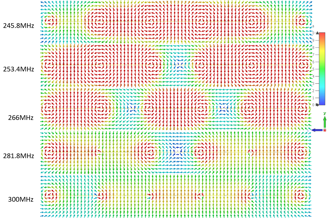
Fig. 3. Magnetic field distribution and direction of five different
resonant frequency of the RF coil array.
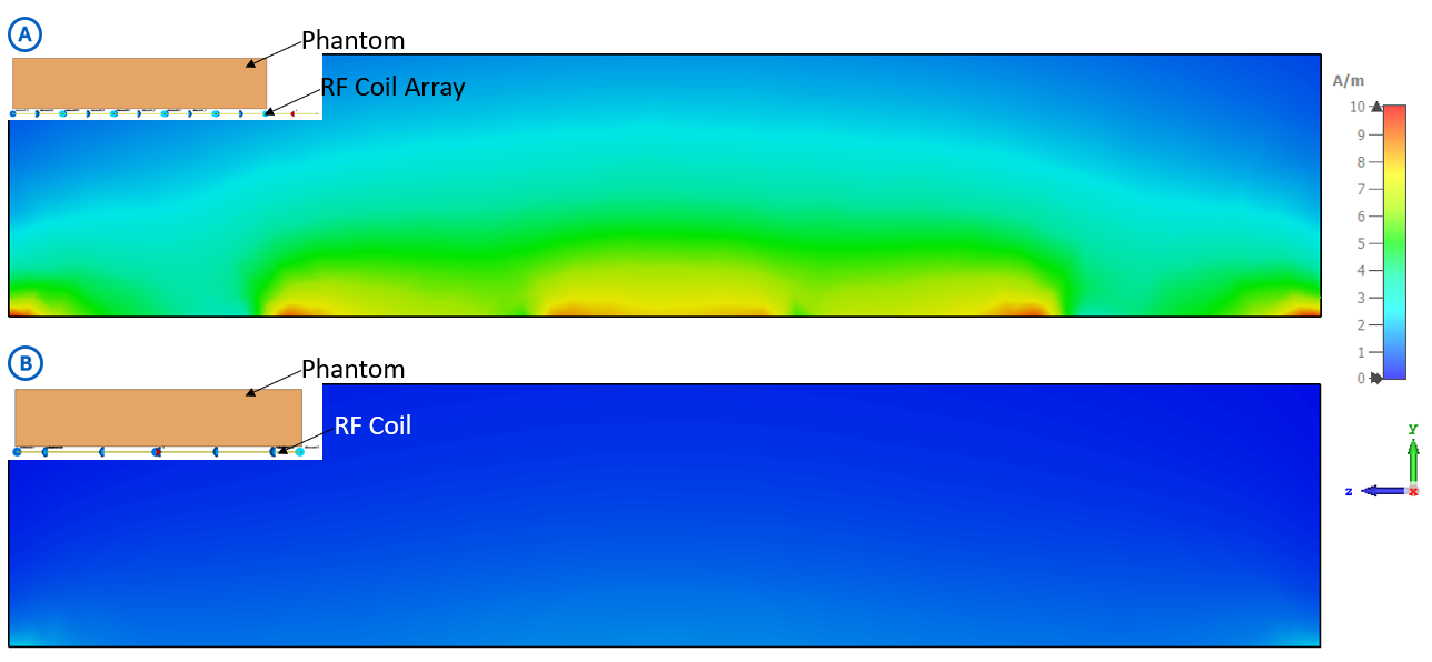
Fig. 4. Magnetic field strength within the phantom of (A) RF coil array and (B)
Large size single coil
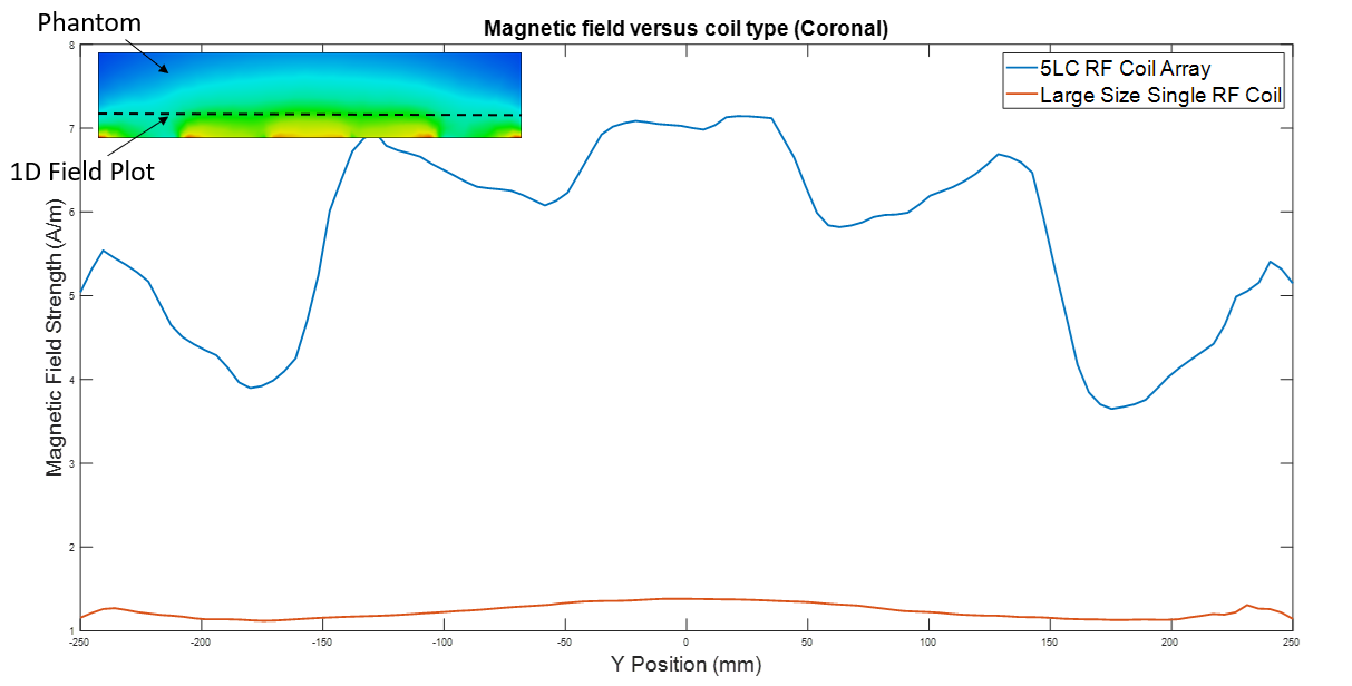
Fig. 5. Magnetic field strength at z-axis when y = 20 and x = 0.
DOI: https://doi.org/10.58530/2023/3910