3908
Investigating the effect of ultra-High Dielectric Constant (uHDC) ceramic disk placement on RF coil performance for optimal MRI applications1Department of Radiology, University of Minnesota, Minneapolis, MN, United States
Synopsis
Keywords: Non-Array RF Coils, Antennas & Waveguides, RF Arrays & Systems
It has been demonstrated that integrating ultra-High Dielectric Constant (uHDC) materials with a RF coil can achieve large improvement in RF magnetic field (B1) and imaging sensitivity. A typical configuration inserts the uHDC materials between the imaging object and the RF coil, resulting in a weak B1 from the coil due to the distance from the object. In this study, we explored different configuration options and found that the best arrangement was to place the uHDC materials outside the coil, leaving no gap between the RF coil and the object, for optimal imaging applications.
Introduction:
The performance of RF coils can be greatly improved by integrating with ultra-High Dielectric Constant (uHDC) materials. We have reported that the permittivity tunable ceramic disk made of composite barium strontium titanate (BST-BT) compounds (Ba0.6Sr0.4TiO3 + 10% w/t BaTiO3) exhibit enhanced RF magnetic transmission (|B1+|) and reception (|B1-|) fields, de-noise effect and large SNR (=|B1-|/(noise level)) gain for 17O imaging at 10.5T and 1H MRI at 1.5T [1, 2]. The B1 fields are improved owing to the contribution of displacement current generated by the uHDC disk; and the image noise reduction is due to the reduced E-field [1]. Traditional arrangement of the uHDC disks with RF coils places the uHDC disks between the coil and imaging object [3, 4]. Herein, we explore different configurations of the two stacked uHDC disks placement relative to a RF coil, and found that the best performance is obtained when the uHDC disks are placed outside the coil, leaving no gap between the coil and imaging object.Methods:
The experimental setups include a 20cm ×15cm loop surface coil tuned and matched to the 10.5T 17O resonance frequency of 60.6MHz. The coil is loaded with an 8cm (diameter)×10cm (height) cylindrical phantom filled with 77 mM NaCl solution. Two stacked BST-BT disks (Disk #1 permittivity (er)=5617, and Disk #2 er=5509) were placed beneath the phantom. Four imaging setups were used for comparison. In Setup 1, the phantom was placed on the top of the coil; in Setup 2, the phantom was lifted away from the coil plane, leaving a gap (equals to the thickness of the stacked uHDC disks) between the coil and the phantom; in Setup 3, the stacked uHDC disks were placed between the coil and the phantom; and in Setup 4, the RF coil and the stacked uHDC disks were placed directly under the phantom, leaving no gap between the phantom and coil.We scanned Setups 1-4 on a Siemens 10.5T human scanner using the FSW-weighted 3D CSI [5] (0.5ms square pulse, 9×9×7 matrix, 12cm FOV, 30k spectral bandwidth, 1024 FID points, and 200ms TR). We acquired 3D CSIs at different pulse voltages including 0 volt (for noise assessment). The 3D CSI post-processing pipeline involves 3D FFT with 10-HZ line broadening in time-domain, and zero padding. The noise level was quantified as the mean of the spectrum noise standard deviations (SD) of all voxels acquired at 0-volt. For Setups 1-4, the distribution of the noise SD of all voxels are fitted with a Gaussian function and the B1 fields are generated by fitting the CSI voxel data acquired at different pulse voltages to a “sine” function. The (ultimate) SNR is defined as the B1- value divided by the noise level of each imaging setup.
Results:
The actual (Fig. 1) and schematic illustration (Fig. 2) of the experimental setups are presented in Figs 1&2 where different positions of the uHDC disks relative to the RF coil and phantom are shown. Figure 3 plots the distributions of the 17O spectral noise SD of all CSI voxels acquired at 0 volt pulse voltage for Setups 1-4. We found that Setup 1 has the highest noise level among all setups, presumably caused by the heavy sample loading effect. Setups 2-4 have similar noise levels, which were around 15% lower compared to the Setup 1. The noise level of Setup 4 is slightly lower than that of Setup 3, as indicated by the vertical red lines in Fig. 3. The noise reduction from Setup 1 to Setup 4 is approximately 17% with the same relative positions between the coil and phantom (Fig. 2).The |B1+|, |B1-| and SNR maps for Setups 1-4 are shown in Fig. 4A-C. Setup 4 has the strongest |B1-| among all setups (Fig. 4A). Setup 4 and Setup 3 have similar level of |B1+| (Fig. 4B). Due to noise level reduction and |B1-| gain, Setup 4 has the highest SNR among all setups (Fig. 4C). The 1D SNR profiles through the base of the phantom are displayed in Fig. 4D, showing that Setups 1-4 have averaged SNR values of 25, 15, 41 and 45 respectively.
Discussion:
We compared the 17O imaging performance for different configurations with varied relative positions of the coil, phantom and uHDC disks; and demonstrated that Setup 4 has 80%, 200% and 12% SNR gains, respectively, compared to the Setup1-3 (Fig. 4D).From the aspect of B1 fields, placing the coil near the phantom (Setup 1) increases B1 fields compared to moving the phantom away from the coil (Setup 2). Adding uHDC disks near the phantom further improves the B1 fields and reduces the imaging noise level as shown in previous study [1, 2, 4]. Therefore, Setup 4 has the least noise compared to all other setups and shows the best outcome.
Conclusion:
The overall findings from this study suggest that to achieve the best imaging SNR and performance, a good practice is to place the uHDC disks outside the transceiver coils, making the transceiver coils most close to the imaging object. Such optimal configuration could advance the integrated uHDC-RF-coil technology for designing whole-brain head coil for imaging applications.Acknowledgements
NIH grants: U01 EB026978, R01 CA240953 and P41 EB027061.References
1. Chen, W., et al., Tunable Ultrahigh Dielectric Constant (tuHDC) Ceramic Technique to Largely Improve RF Coil Efficiency and MR Imaging Performance. IEEE Trans Med Imaging, 2020. 39(10): p. 3187-3197.
2. Li, X., et al. Dielectric transreceiver resonant coil using an ultrahigh Er ceramic disk for 17O imaging at 10.5T and comparison with a single-loop surface coil. in The Proceedings of the 31st Annual Meeting of ISMRM. 2022. London, UK.
3. Lakshmanan, K., et al., Improved whole‐brain SNR with an integrated high‐permittivity material in a head array at 7T. Magnetic Resonance in Medicine, 2021. 86(2): p. 1167-1174.
4. Lee, B.-Y., et al., Large improvement of RF transmission efficiency and reception sensitivity for human in vivo 31 P MRS imaging using ultrahigh dielectric constant materials at 7 T. Magnetic Resonance Imaging, 2017. 42: p. 158-163.
5. Hendrich, K., et al., Spectroscopic imaging of circular voxels with a two-dimensional Fourier-series window technique. J Magn Reson B, 1994. 105(3): p. 225-32.
Figures
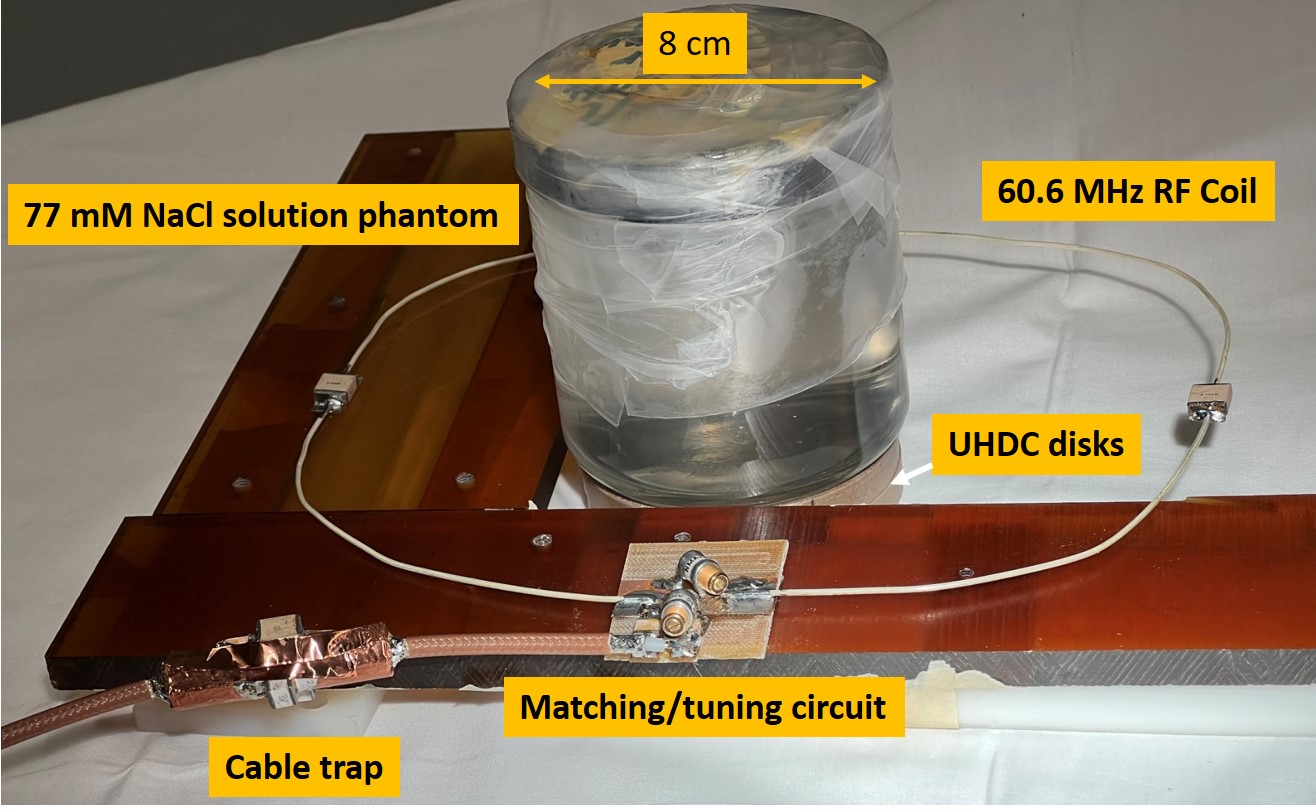
Figure 1. Experimental setup included a 77mM NaCl solution phantom, a RF surface coil tuned to 60.6 MHz for 10.5T 17O imaging application, and two-stacked ultra-high dielectric constant (uHDC) disks. A 60.6MHz cable trap was added on the co-axial cable next to the coil feed for coil stability.
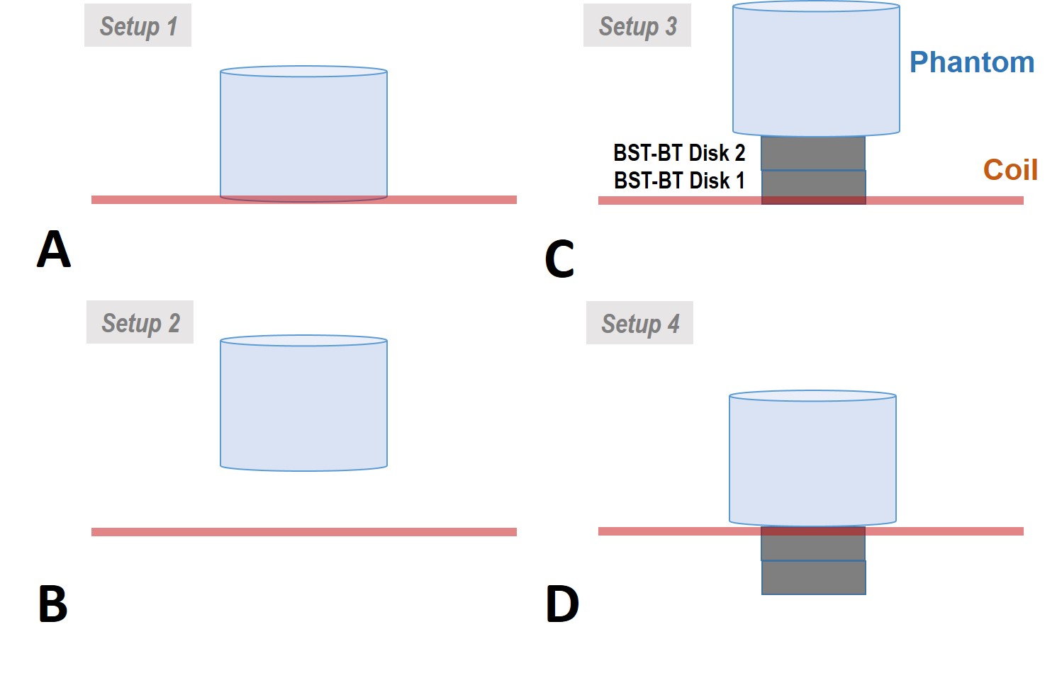
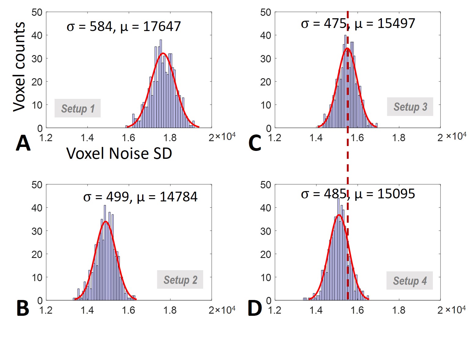
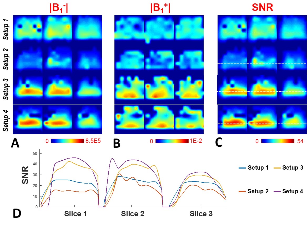
Figure 4. Three representative slices (sagittal orientations) of |B1-| (A), |B1+| (B) and SNR (C) maps, and the 1D SNR profiles (D) through the middle of the phantom (along the white dash lines in C) for Setup 1-4 are presented.