3903
Performance comparisons of different single-channel coils using different materials
Chunhu Song1,2, Qiaoyan Chen1,2, Shao Che1,2,3, Haining Wang3, Xiaoliang Zhang4, and Ye Li1,2
1Paul C. Lauterbur Imaging Research Center, Shenzhen Institutes of Advanced Technology, Chinese Academy of Sciences, Shenzhen, China, 2Key Laboratory for Magnetic Resonance and Multimodality Imaging of Guangdong Province, Shenzhen, China, 3Shanghai United Imaging Healthcare, Shanghai, China, 4Department of Biomedical Engineering, State University of New York at Buffalo, New York, NY, United States
1Paul C. Lauterbur Imaging Research Center, Shenzhen Institutes of Advanced Technology, Chinese Academy of Sciences, Shenzhen, China, 2Key Laboratory for Magnetic Resonance and Multimodality Imaging of Guangdong Province, Shenzhen, China, 3Shanghai United Imaging Healthcare, Shanghai, China, 4Department of Biomedical Engineering, State University of New York at Buffalo, New York, NY, United States
Synopsis
Keywords: RF Arrays & Systems, RF Arrays & Systems
The ultra-flexible RF coil can fit the image subjects well and thus improve signal-to-noise ratio (SNR). In this study, four types of single-channel receiver coils using different materials with the same size were constructed. Phantom studies were performed on a 3T MRI system. As a result, the liquid metal coil can achieve a most similar performance as the conventional copper coil, while the liquid metal coil is more flexible. This demonstrates that the liquid metal coil has a good application potential in imaging curved anatomical structures.Introduction
In recent years, flexible RF coils have been developed rapidly in order to improve signal-to-noise ratio (SNR) and comfort of patient1. Compared to rigid RF coils, flexible RF coils can be conformably adjusted to fit the patient, thus improve SNR and comfort. In this study, four types of single-channel receiver coils using different materials with the same size were constructed, including copper skin, liquid metal, copper braided tape and copper foil DC wire. Phantom studies were performed on a 3T MRI system. The unloaded/loaded Q factor and SNR of these four coils with different distances from the phantom were evaluated. Moreover, the performance of the coils with different capacitance numbers on the loop was also evaluated.Methods
Figure 1 shows the photographs of the four types of single-channel receiver using different materials: copper skin (pure copper, conductivity: 5.7x10⁷ S/m), liquid metal2(gallium-indium alloy, conductivity: 4.3x10⁷ S/m, Beijing Dream Ink Technology), copper braided tape (bare copper shielding sleeve, conductivity: 4.2x10⁷ S/m, Shuoten Electronic Technology), and copper foil DC wire3 (multi-strand braid, outer diameter 1.75mm, conductivity: 2.2x10⁶ S/m). Figure 1a shows the coils with 1 capacitor on the loop and Figure 1b shows the coils 2 capacitors on the loop. The coils with an inner diameter of 10 cm and were tuned at 128.2 MHz and matched to 50 ohms on a 3 T MRI scanner (uMR 790, Shanghai United Imaging Healthcare, Shanghai, China).The measurement of unloaded/loaded Q factor of the coils of different materials was implemented by using the vector network analyzer. The loaded quality factors were tested for the coils with a 10 mm distance from a rectangle phantom (10 cm wide, 10 cm thick and 20 cm length), which was filled with 1.24 g/L NiSO4·6H2O and 2.62 g/L NaCl (approximate conductivity 0.62 S/m and relative permittivity 83 at 128.2 MHz).
For SNR maps, a 2D gradient echo (GRE) sequence was applied for signal acquisitions with the parameters: TR/TE=300/6.5 ms, flip angle=30°, slice thickness=5 mm, matrix=256×256, FOV=200 mm×200 mm. The noise images were obtained by setting the flip angle to zero. The SNR maps in transversal and sagittal planes were tested for the coils with 10 mm, 15 mm, 25 mm distances from the phantom. The mean SNR value was calculated in a rectangle region of interest (ROI).
Results
Table 1 shows the unload/loaded Q and Qratio of the coils with 1 capacitor and with 2 capacitors on the loop at a 10 mm distance from the phantom. Unload Q is related to the coil material impedance. The greater the material impedance, the smaller the value of unload Q. Loaded Q is related to the phantom. The unload Q and load Q values of the coils with 2 capacitors on the loop are higher than those of the coils with 1 capacitor on the loop.Figure 2 shows the SNR maps of the coils with 1 capacitor and with 2 capacitors on the loop at a 10 mm distance from the phantom. Table 2 shows comparisons of the SNR values in the ROI for the coils using different materials, using the SNR value of the copper skin coil as the benchmark 1. As shown in the table, the liquid metal coil can achieve a most similar performance as the copper skin coil.
Figure 3 shows the SNR maps of the coils with 2 capacitors on the loop at 15 mm and 25 mm distances from the phantom. Known from Figure 2 and Figure 3, the closer the coil is to the imaging subject, the higher the SNR.
Conclusions
Four types of single-channel receiver coils using different materials with the same size were constructed and evaluated. The liquid metal coil can achieve a most similar performance as the conventional copper coil, while the liquid metal coil is more flexible. This demonstrates that the liquid metal coil has a good application potential in imaging curved anatomical structures.Acknowledgements
This work is supported by National Key Research and Development Program of China, 2021YFE0204400; the Strategic Priority Research Program of Chinese Academy of Sciences, XDB25000000; National Natural Science Foundation of China, U22A20344; Youth Innovation Promotion Association of CAS No. Y2021098; Key Laboratory Project of Guangdong Province, 2020B1212060051; Shenzhen city grant, RCYX20200714114735123.References
1. Darnell D, Truong T-K, SONG A W. Recent Advances in Radio-Frequency Coil Technologies: Flexible, Wireless, and Integrated Coil Arrays. Journal of Magnetic Resonance Imaging,2022,55(4):1026-1042.
2. PorT A, Luechinger R, AlbisettliL L, et al. Detector clothes for MRI: A wearable array receiver based on liquid metal in elastic tubes. Scientific Reports,2020,10(1):8844.
3. Tan Y, Chen Q, Zhao R, Lu H, Fan X, Chen J, Liu X, Zheng H, Li Y. A 24-channal ultra-light flexible receiver coil array for human body imaging at 5T. Proc. 30th Annual Meeting of ISMRM, London, 2022, p.3225.
Figures
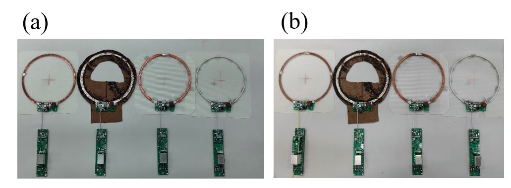
Figure 1. (a) Four different material coils (1 capacitor on the loop). (b) Four different material coils (2 capacitors on the loop)
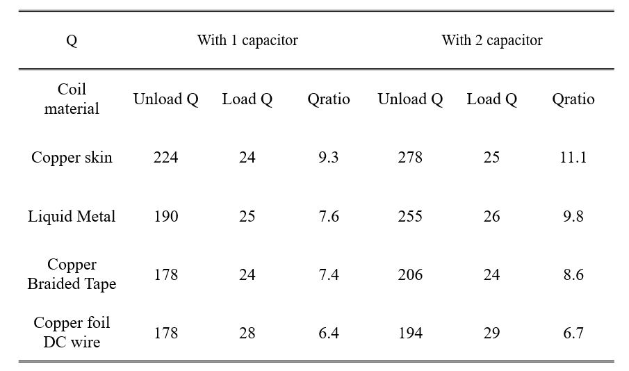
Table 1. The unload/loaded Q and Qratio of the coils with 1 capacitor and 2 capacitors on the loop at a 10 mm distance from the phantom.
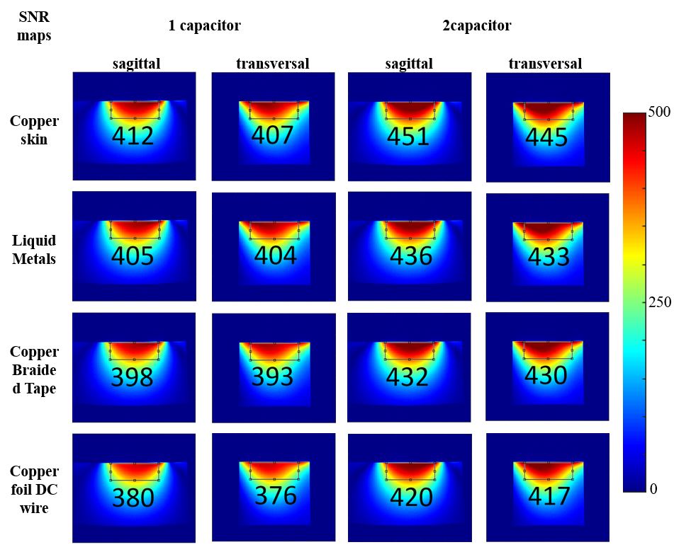
Figure 2. the SNR maps of the coils with 1 capacitor and with 2 capacitors on the loop at a 10 mm distance from the phantom. The mean SNR value in the ROI is shown at the corresponding position.
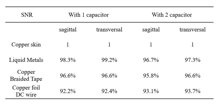
Table 2. Comparisons of the SNR values in the ROI for the coils using different materials, using the SNR value of the copper skin coil as the benchmark 1.
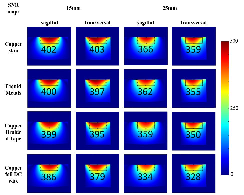
Figure 3. the SNR maps of the coils with 2 capacitors on the loop at 15 mm and 25 mm distances from the phantom.
DOI: https://doi.org/10.58530/2023/3903